
Specifications
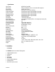
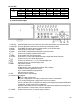


DVR16M 7 GB
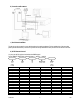
PIN 5: ALARM INPUT 2: By connecting ALARM INPUT 2 (pin 5) to GND (pin 1), the DVR16M will start recording
and the buzzer will be on. Triggering depends on the set level (high/low) under Menu/Camera/Alarm.
PIN 6: ALARM INPUT 16: By connecting ALARM INPUT 16 (pin 6) to GND (pin 1), the DVR16M will start recording
and the buzzer will be on. Triggering depends on the set level (high/low) under Menu/Camera/Alarm.
PIN 7: ALARM INPUT 14: By connecting ALARM INPUT 14 (pin 7) to GND (pin 1), the DVR16M will start recording
and the buzzer will be on. Triggering depends on the set level (high/low) under Menu/Camera/Alarm.
PIN 8: ALARM INPUT 12: By connecting ALARM INPUT 12 (pin 8) to GND (pin 1), the DVR16M will start recording
and the buzzer will be on. Triggering depends on the set level (high/low) under Menu/Camera/Alarm.
PIN 9: ALARM INPUT 10: By connecting ALARM INPUT 10 (pin 9) to GND (pin 1), the DVR16M will start recording
and the buzzer will be on. Triggering depends on the set level (high/low) under Menu/Camera/Alarm.
PIN 10: PIN OFF
PIN 11: RS232-TX + PIN 23: RS232-RX: This device can be controlled remotely by an external device or control
system, such as a control keyboard, using RS-232 serial communications signals.
PIN 12: RS485-A + PIN 24: RS485-B: This device can be controlled remotely by an external device or control
system, such as a control keyboard, using RS-485 serial communications signals.
PIN 13: EXTERNAL ALARM NO + PIN 25: EXT. ALARM COM: During normal functioning COM is connected with
NC and not with NO. When there is an alarm trigger, COM disconnects from NC and connects with NO.
PIN 14: PIN OFF
PIN 15: ALARM INPUT 7: By connecting ALARM INPUT 7 (pin 15) to GND (pin 1), the DVR16M will start recording
and the buzzer will be on. Triggering depends on the set level (high/low) under Menu/Camera/Alarm.
PIN 16: ALARM INPUT 5: By connecting ALARM INPUT 5 (pin 16) to GND (pin 1), the DVR16M will start recording
and the buzzer will be on. Triggering depends on the set level (high/low) under Menu/Camera/Alarm.
PIN 17: ALARM INPUT 3: By connecting ALARM INPUT 3 (pin 17) to GND (pin 1), the DVR16M will start recording
and the buzzer will be on. Triggering depends on the set level (high/low) under Menu/Camera/Alarm.
PIN 18: ALARM INPUT 1: By connecting ALARM INPUT 1 (pin 18) to GND (pin 1), the DVR16M will start recording
and the buzzer will be on. Triggering depends on the set level (high/low) under Menu/Camera/Alarm.
PIN 19: ALARM INPUT 15: By connecting ALARM INPUT 15 (pin 19) to GND (pin 1), the DVR16M will start
recording and the buzzer will be on. Triggering depends on the set level (high/low) under Menu/Camera/Alarm.
PIN 20: ALARM INPUT 13: By connecting ALARM INPUT 13 (pin 20) to GND (pin 1), the DVR16M will start
recording and the buzzer will be on. Triggering depends on the set level (high/low) under Menu/Camera/Alarm.
PIN 21: ALARM INPUT 11: By connecting ALARM INPUT 11 (pin 21) to GND (pin 1), the DVR16M will start
recording and the buzzer will be on. Triggering depends on the set level (high/low) under Menu/Camera/Alarm.
PIN 22: ALARM INPUT 9: By connecting ALARM INPUT 9 (pin 22) to GND (pin 1), the DVR16M will start recording
and the buzzer will be on. Triggering depends on the set level (high/low) under Menu/Camera/Alarm.
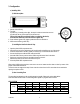
4. System Set-up
a) Open Main Menu
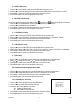
Press the MENU button on the front of the device. The screen
you see on the right will be displayed. You will need to enter a
password to access the main menu. Press #or$ (left/right) to
change digits and"or!(up/down) to change the value of the
digit. Press ENTER to confirm the password.
e.g.: password: 0000 (default: 0000)
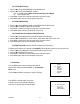
After entering the correct password and confirming it by pressing
ENTER, this display will appear:
PASSWORD: 0000
(MENU)
► SEARCH
TIMER
RECORD
CAMERA
SYSTEM
EVENT