
Specifications
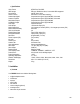


DVR16M 6 GB
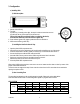
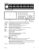
c) Back Panel Description
1. LOOP connectors: bring the channel input signal out again to connect to an additional VCR, monitor etc.
2. VIDEO IN: to connect a video source such as a camera.
3. 75/HI switches: set these switches to the right position for the destination device when using the loop function.
4. POWER: connect the provided adapter to this connector and plug it into the mains.
5. External I/O: the device can be controlled remotely by an external device or trigger mechanism.
6. CALL: to connect a call monitor.
7. MONITOR: to connect the main monitor.
8. AUDIO IN: to connect an audio source such as a microphone (only when IPS is 15A for NTSC or 12A for PAL).
9. AUDIO OUT: to connect to a monitor or speaker system (only when IPS is 15A for NTSC or 12A for PAL).
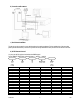
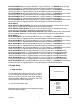
25-pin COM port 9-pin COM port
PIN 1: GND: GROUND
PIN 2: ALARM INPUT 8: By connecting ALARM INPUT 8 (pin 2) to GND (pin 1), the DVR16M will start recording
and the buzzer will be on. Triggering depends on the set level (high/low) under Menu/Camera/Alarm.
PIN 3: ALARM INPUT 6: By connecting ALARM INPUT 6 (pin 3) to GND (pin 1), the DVR16M will start recording
and the buzzer will be on. Triggering depends on the set level (high/low) under Menu/Camera/Alarm.
PIN 4: ALARM INPUT 4: By connecting ALARM INPUT 4 (pin 4) to GND (pin 1), the DVR16M will start recording
and the buzzer will be on. Triggering depends on the set level (high/low) under Menu/Camera/Alarm.