
Operating instructions
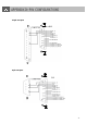


PIN 1. RS232-TX : RS-232
DVR can be controlled remotely by an external device or control system, such as a control keyboard, using RS-
232 serial communications signals.
PIN 2. RS232-RX : RS-232
DVR can be controlled remotely by an external device or control system, such as a control keyboard, using RS-
232 serial communications signals.
PIN 3, 4, 5, 6 ALARM INPUT
To connect wire from ALARM INPUT (PIN 3, 4, 5, 6) to GND ( PIN 9 ) connector.When alarm has been triggered,
signal becomes “Low”, and it will stop all alarm activities. Under normal operation,signal remains “High”.
PIN 7. EXTERNAL ALARM NC
Under normal operation COM connect with NC and disconnect from NO. But when alarm is triggered, COM
disconnect with NC, and connect with NO.
PIN 8. EXTERNAL ALARM NO
Under normal operation, COM will disconnect from NO. But when Alarm is triggered, COM will connect with NO.
PIN 9. GND
GROUND
PIN 10. RS485-B
DVR can be controlled remotely by an external device or control system, such as a control keyboard, using RS-
485 serial communications signals.
PIN 11. RS485-A
DVR can be controlled remotely by an external device or control system, such as a control keyboard, using RS-
485 serial communications signals.
PIN 14. ALARM RESET (INPUT)
To connect wire from ALARM RESET ( PIN 14 ) to GND ( PIN 9 ) connector, it can disable ALARM. An external
signal to ALARM RESET ( PIN 14 ) can be used to reset both ALARMOUTPUT signal and DVR’s internal buzzer.
When alarm has been triggered, signal becomes “Low”, and it will stop all alarm activities. Under normal operation,
signal remains “High”.
PIN 15. EXTERNAL ALARM COM
Under normal operation COM connect with NC and disconnect from NO. But when alarm is triggered, COM
disconnect from NC, and connect with NO.
37