Intelligent & Multiplex 4 CH MPEG-2 DVS 500 V1.
WARNING All the safety and operating instructions should be read before operation. The improper operation may cause permanent damage. • This adaptor is only for this machine. Do not use it for other electronic products or it will damage other products. • Please lift and place this equipment gently. • Do not expose this equipment to direct sunlight. • Do not use this equipment near water or in contact with water. • Do not spill liquid of any kind on the equipment.
TABLE OF CONTENTS 1. What do you get ? FEATURES 1 PACKAGE CONTENT 1 2. Before Operation INSTALLATION GUIDE 2 FRONT PANEL 3 REAR PANEL 5 3. Basic Operation GETTING STARTED OPERATION 6 7 RECORDING 7 PLAYBACK 8 4.
5. Advanced Operation OPERATION OPTIONS 26 2X ZOOM 26 VIDEO LOSS 26 SEARCH 27 USB BACKUP 30 KEY LOCK 31 RS-232 PROTOCOL 31 TROUBLE SHOOTING 32 SPECIFICATIONS 33 6.
What do you get ? FEATURES PA • MPEG-2 compression format • USB Backup ( backup files by USB Flash Drive and USB HDD devices). • High resolution: 720 X 480 pixels 720 x 576 pixels • Duplex function (record and playback) • Picture-in-Picture (PIP) in live • Motion detection function • Alarm input & output function • Video loss detected on each channel • Linear Zoom (2x) • Recording rate: Up to 30 frames/sec (NTSC) ; Up to 25 frames/sec (PAL).
Before Operation INSTALLATION GUIDE 1. Shown below is an example of connecting the DVR to existing Observation System. 2. Install HDD (The compatible HDD models are listed in the following table). Please refer to page.34 Appendix A for installation instructions. Note: 1. The HDD must be installed before turning on the DVR. If HDD is not installed, the DVR would function as a 4 CH multiplexer. 2. Users need to set the HDD on the Master mode for system detecting.
FRONT PANEL 1. LED LIGHT The LED Light is ON under following conditions. •HDD : HDD is reading or recording. •HDD Full : HDD is full •ALARM : To turn off the ALARM LED light, please refer to page.15 and set the ALARM mode as OFF. •TIMER : When Timer is Enabled •PLAY : Playing mode •REC : Recording mode 2. MENU Press MENU to enter main menu. 3. ENTER Press ENTER for confirmation 4. SEARCH Press SEARCH for searching recorded video. 5. ZOOM Press the ZOOM button Enlarge the picture (2X). 6.
. SLOW To slow down the speed of playing mode. 9. FF / ► •FF : Play video fast forward. (Press FF button again to adjust speed as 3, 45, 600 times) • ► : Under setup mode, it works as Right button. 10. REW / ◄ •REW : Play video fast backward. (Press REW button again to adjust speed as 15, 90, 600 times) • ◄ : Under setup mode, it works as Left button. 11. STOP / ▼ •STOP : Under DVR Play mode, it can stop the action. • ▼ : Under setup mode, it works as Down button. 12.
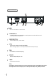
REAR PANEL 7 1 2 MAIN 3 4 CALL RISK OF E LEC TR IC S HOCK DO NOT OP EN USB USB PORT WA R N IN G : TO RE D U C E T HE R IS K OF E L EC TR IC SH OC K , D O N OT R E MO VE C OV ER ( OR B AC K ). NO U SE R -S ER V IC EA BL E PAR TS IN S ID E. R EF ER S ER V IC IN G TO QU AL IF IED S ER V ICE P ER S ON N EL . IN OU T EXTERNAL I/O 1 2 DC 19V 3 4 5 1. USB Connect to a USB HDD or a USB Flash Drive. 2.
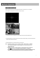
Basic Operation GETTING STARTED Before using the DVR, please have a HDD installed ready; otherwise, it will function as a 4 CH multiplexer (refer to Appendix A and Appendix B for installation or removal of a HDD). 1. Connect the AC power cord and plug into an electrical outlet. The power LED indicator light will be on. 2. It takes approximately 5 to 15seconds to boot the system with the message:”Booting”. The Power LED will turn from orange to green and Alarm LED will be on. 3.
OPERATION RECORDING The DVR offers 2 recording modes(Timer, Manual). Under the recording status, if power is off accidentally, the recorded video will still be stored in the HDD. DVR will return to previous recording setting after power restores. The first character: ( Frame/Sec) A : 30 25 B : 15 12 C : 5 4 The second character: (Record Quality) a : Best b : High c :Normal d : Basic 007.
PLAY BACK Press the “PLAY” button to display the last video. The screen will display the last video of a channel which is in display. When all channels are on screen display, and users press the “PLAY” button, the menu (PLAY MODE) will show up for users to select channels. When changing the channels, users can either press the buttons “1- 4” on the front panel or enter the “PLAY MODE”menu for displaying. Press “ENTER” button to enlarge the video to full screen.
1. FF (FAST FORWARD) & REW (FAST REWIND) Increase the speed of Fast Forward and Rewind on the DVR by pressing the “FF” button. In the Play mode, press “ FF ” once to get 3X speed forward and press twice to get 45X speed, and the maximum speed can reach 600X. Press “REW ” once to get 15X speed rewind and press twice to get 90X speed, and the maximum speed can reach 600X. 2. SLOW FORWARD Slow down the speed of Forward on the DVR by pressing the “SLOW” button.
Detailed Menu Setup MAIN MENU Press “MENU” button to enter the main menu at first time. The default password is 000000. There are 7 options available in the Main Menu. RECORD -------- Record Scheduling CAMERA -------- Camera Setup DETECTION ---- Motion / Alarm Setup DISPLAY -------- Display Mode Setup USER ------------ User Password Setup SYSTEM -------- System Setup EVENT ---------- Event List Outlined below are the buttons used for Menu setting : ▲ ” “ ” : Move the cursor.
MAIN OPTIONS ▼ Press the “▲” “▼” “ ” “ ▼ RECORD ” buttons to move the cursor. Press the “+” “-” buttons to change the digit. Press the “MENU” button to confirm the changes/ to exit the menu. 1. STOP RECORD(MANUAL RECORD) The system will stop manual recording function during the recording period if the setting is “YES”. And then, press the “ENTER” button to save the changed value. Note: 1.
▼ Press “▲” “▼” “ ” “ ▼ TIMER SETUP ” buttons to move the cursor. Press “+” “-” buttons to change the digit. Press “MENU” button to confirm the changes/ to exit the menu. 1. DAY Choose the day for recording. The options are: MON(Monday) , TUE (Tuesday), WED (Wednesday), THU (Thursday), FRI (Friday), SAT (Saturday), SUN (Sunday), MO-FR (Monday to Friday), SA-SU (Saturday to Sunday), OFF, and DAILY(on each day). * Date could be changed by “+” and “-” buttons. 2. START The beginning of recording time.
CAMERA ▼ ▼ Press the “ ” “ ” buttons to move the cursor. Press the “+” “-” buttons to change the option/digit. Press the “MENU” button to confirm the changes/ to exit the menu. 1. TITLE Assign a title to each channel. The default title is the camera’s number (Up to 8 characters). 2. REC (RECORD) Select a channel to record. ON : when the timer input is triggered, DVR will record a video. OFF : DVR will not record. 3. BR (BRIGHTNESS) Adjust the brightness of each channel. The level is from 0 to 63. 4.
DETECTION Press the “▲” “ ▼ ” buttons to move the cursor. Press the “+” “-” buttons to change the option. Press the “MENU” button to confirm the changes/ to exit the menu. 1. DET (DETECTION) The motion detection on each channel can be turned ON or OFF individually. 2. AREA Press the “ENTER” button to set target-area. In this function, it is defaulted to detect the whole area.
: navigates between targets. ▼ ▼ ▲▼ - : turns all targets on the screen ON/ OFF. + : press once to set a motion target, press twice to set a row of motion target. 3. LS (Level Sensitivity) Comparing the difference between two images to allow the system to start motion detection function. Lower number = higher sensitivity for motion detection. The highest sensitivity setting is 0, the lowest sensitivity setting is 15. The default value is 06. 4.
DISPLAY ▼ ▼ Press the “▲” “ ▼ ” “ ” “ ” buttons to move the cursor. Press the “+” “-” buttons to change the option/digit. Press the “MENU” button to confirm the changes/ to exit the menu. 1. TITLE DISPLAY Set the title shown on monitor. 1 2. OSD COLOR Select the OSD (On Screen Display) color. The options are WHITE, RED, YELLOW, CYAN, BLUE, PINK, GRAY, ORANGE. 3. CURSOR COLOR Select the cursor color. The options are RED, YELLOW, GREEN, CYAN, BLUE, PINK, GRAY, ORANGE .
PIP OPTION Press the “▲” “▼” buttons to move the cursor. Press the “+” “-” buttons to change the option. Press the “MENU” button to confirm the changes/ to exit the menu. 1. FULL SCREEN The full screen background picture display. 2. PIP SCREEN The picture with a 1/9 size screen “insert”. 3. POSITION There are six position settings : D/L (Down/Left), D/M (Down/Middle), D/R (Down/Right), U/L (Up/Left), U/M (Up/Middle), U/R (Up/Right).
DWELL OPTION ▼ ▼ Press the “▲” “▼” “ ” “ ” buttons to move the cursor. Press the “+” “-” buttons to change the option. Press the “MENU” button to confirm the changes/ to exit the menu. 1. NORM To set up the DWELL time period that each channel auto sequentially shows on call monitor. The level is from 01 to 24 Sec or OFF. 2. ALARM To set up the DWELL time period when alarm input is triggered. The level is from 01 to 24 Sec or OFF.
USER ▼ ▼ Press the “▲” “▼” “ ” “ ” buttons to move the cursor. Press the “+” “-” buttons to change the option/digit. Press the “MENU” button to confirm the changes/ to exit the menu. 1. USER To set up the user’s account for controlling. It allows 7 users setting. Supervisor – Control all the functions. Other Users – View all functions except the menu setting and event list cleaning. 2. PASSWORD To set the security password for each account. The maximum length of user’s password is 6 digits.
SYSTEM ” “ ” buttons to move the cursor. ▼ ▼ Press the “▲” “▼” “ Press the “+” “-”buttons to change the setting Press the “MENU” button to confirm the changes/ to exit the menu 1. KEY MUTE To set the KEY MUTE. When the setting is “ON”, there will be no sound when you press any key. 2. BUZZER (see p.22) To enter the buzzer setup menu. 3. MESSAGE LATCH The default setting of messages displaying is 10 seconds when the setting is “ON”. 4. DATE DISPLAY Set the date display.
8. SYSTEM RESET Reset all system settings back to factory default setting. 9. LANGUAGE Select one language for menu displaying. The options are ENGLISH and CHINESE. The system will automatically save the setting. 10. UPGRADE(see p.24) To enter the upgrade setup menu. 11. REMOTE(see p.23) To enter the remote setup menu.
BUZZER SETUP 1. BUZZER Set the BUZZER “ON”, it will buzz when event occurs. 2. EXT ALARM To set the EXT ALARM. It will be trigged by event occurrence when the setting is “ON”. 3. VLOSS ALARM To set the VLOSS ALARM. When the setting is “ON”, the alarm will start after setting Buzzer, EXT Alarm or Alarm Duration. 4. MOTION ALARM To set the MOTION ALARM. When the setting is “ON”, the alarm will start after setting Buzzer and EXT Alarm.
REMOTE SETUP Press the “▲” “▼” buttons to move the cursor. Press the “+” “-” buttons to change the option. Press the “MENU” button to confirm the changes/ to exit the menu. 1. REMOTE MODE Set the remote mode for connection with computer via RS-232 or RS-485. (refer to page. 30 for RS-232 & RS-485 Remote Control). 2. BAUD RATE Set the remote protocol transmitting baud rate. Available options are 115200, 57600, 19200, 9600, 4800, 2400, 1200. 3. ID To control different DVR by setting remote protocol.
UPGRADE SETUP User can upgrade the DVR software by USB storage device. YES: Upgrade No : Cancel It will take few minutes to upgrade the whole system. Users cannot unplug the power cord, or turn off the power during the period of upgrading. It will reset the system setting will be disable when the system is upgraded. Therefore, the users have to reset all settings after upgrading. CHECK CRC: The system will check the firmware status to ensure the quality of system.
EVENT Press the “▲” “▼” buttons to move the cursor. Press the “ENTER” button to get into the submenu The EVENT shows the recording list of different types. The VLOSS section lists the record of video loss. The ALARM LOG section lists the record of triggering by external I/O alarm. The MOTION LOG section lists the record of triggering by motion detection. The ALL LOG section lists all types of records. The DELETE ALL option will delete all records. ▼ ▼ A single page can display 12 recorded events.
Advanced Operation OPERATION OPTIONS 2X ZOOM Press the “ZOOM” button, it displays zoomed picture on main picture and a small inserted window. The inserted window contains a movable 1/4 view size of the appointed camera. The range is 2X. 2004 MAY-27 [THU] PM 01:45:37 CAMERA01 ▼ ▼ • Press the “ZOOM” button again to exit the zoom pointer. • Press Camera 1-4 button to select a channel. • Press ▲▼ buttons to move the zoom position.
SEARCH Press “SEARCH” button to play the recording. Select a channel for searching a video record. Press “▲” “▼” buttons to select camera. Press the “ENTER” button to get into menu/ submenu Press the “MENU” button to confirm the changes/exit the menu [SEARCH MODE] Press the “ENTER” button to get into each submenu. 1. EVENT SEARCH Display all the videos, which have been motion triggered on the recording mode. 2. TIME SEARCH Enter a time period for searching a video. 3. LIST ALL List all video records.
1. Select Enter a period of time for searching a video. If the users enter an inexistent period, it will show “PRESS MENU KEY TO RETURN”. After enter the “MENU” button, the screen will go back to the previous screen.
Press the “▲” “▼” buttons to select one record. Press the “ENTER” / “PLAY” buttons to display. 1. Y/M/D The Month and the Date display(Year/Month/Date). 2. HO:MI:SE The beginning of recording time(Hour:Minute:Second). 3. MI:SE The duration of playing time(Minute:Second). 4. TYPE D1: Multiplex mode (input images of a channel at a time).
USB BACKUP Users may have to format the USB memory device( USB Sticker and USB HDD devices ) by PC before connecting to the DVR. Press both “ENTER”+ “SEARCH” buttons, enter the USB BACKUP mode. Users can save files into the USB storage device, and read files by personal computer. The system will detect the USB storage device automatically. it will show “DETECTING USB DEVICE” The symbol [ ] shows the available space of the USB storage device. And press “ENTER”, you can see this screen.
KEY LOCK For advanced security, users can “Lock” the buttons on your DVR. Key-Lock prevents other people from using the system. Press “ENTER” + “MENU” at the same time to enable Key Lock. Press “ENTER” + “MENU” at the same time and key in password (Default : 000000), and then press “ENTER“ to disable Key Lock. NOTE: To switch to different USER, press “ENTER” + “MENU” buttons to “KEY LOCK” and then enter the different user’s password to UNLOCK.
TROUBLE SHOOTING When malfunction occurs, it may not be serious and can be corrected easily. The table below describes some typical problems and their solutions. Please check on them before contacting your DVR dealer. PROBLEM SOLUTION l Check power cord connections. l Confirm that there is power at the outlet. Not working when pressing any button l l Check if it is under Key Lock mode. Press "MENU" & "ENTER" to exit Key Lock mode.
SPECIFICATIONS Video Format Hard Disk Storage NTSC/EIA or PAL/CCIR IDE type, UDMA 66, supported a over 250 GB HDD Resolution 720 x 480 pixels , 720x576 pixels Recording Mode Camera Input Signal Manual / Timer Main Monitor Output Composite video signal 1 Vp-p 75Ω BNC Call Monitor Output Composite video signal 1 Vp-p 75Ω BNC 1 port. Support USB 1.
APPENDIX A– INSTALL THE HDD Follow these steps carefully in order to ensure correct installation. Fig. 1 Fig. 2 Fig. 3 Fig. 4 Fig. 5 Step 1 Remove the lid and unscrew the screws from HDD bracket module . Step 2 Insert the HDD into the HDD bracket and screw the four screws. (refer to the Fig. 1, Fig. 2). Step 3 Connect the HDD power cable to the HDD (refer to the Fig. 3), and attach the HDD connector to the 40-pin cable, Step 4 Screw the HDD and the DVR machine together (refer to the Fig. 3).
APPENDIX C– RECORDING SPEED The Recording Time is different based on Recording Speed, Recording Quality and Recording Mode. Please refer to the following table. HDD capability is 250GB.
APPENDIX D– PIN CONFIGURATIONS 15 pin com port • • DVR • • 9 pin com port • • DVR DQR • • 36
PIN 1. RS232-TX : RS-232 DVR can be controlled remotely by an external device or control system, such as a control keyboard, using RS232 serial communications signals. PIN 2. RS232-RX : RS-232 DVR can be controlled remotely by an external device or control system, such as a control keyboard, using RS232 serial communications signals. PIN 3, 4, 5, 6 ALARM INPUT To connect wire from ALARM INPUT (PIN 3, 4, 5, 6) to GND ( PIN 9 ) connector.
APPENDIX E– NETWORK APPLICATION Video Web Server Features • Compatible with most of CCTV Products; empower any video output device watching and controlling on the Internet or LAN • Auto Network Reconnection (ANR) • Upgrade firmware & AP from FTP site via Video Web Server • Support Watch dog function • Support Dynamic IP address via a router.