
User manual
15
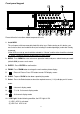
PIN 1. GND
GROUND
PIN 2. – PIN 9 , PIN 15 – PIN 22. ALARM INPUTS
When a connection is made between an alarm input and to GND (PIN 1) on the D25
connector, the DMR will start recording and the buzzer will sound.
When Menu/ Camera/ Alarm is set up to “Low”: When alarm input signal is “ Low ”,
the unit starts to record and sounds buzzer.
When Menu/ Camera/ Alarm is set up to “High”: When alarm input signal is “ High ”,
the unit starts to record and sounds buzzer.
PIN 10. NO Connection
PIN 11/23. RS232-TX / RS232-RX
DMR can be controlled remotely by an external device or control system, such as a
control keyboard, using RS-232 serial communications signals.
PIN 12/24. RS485-A / RS485-B
DMR can be controlled remotely by an external device or control system, such as a
control keyboard, using RS485 serial communications signals.
PIN 13/25. EXTERNAL ALARM NO
Under normal operation COM is disconnected from NO. But when an Alarm is
triggered, COM connects with NO.
PIN 14. NO CONNECTION