Digital Multiplex Recorder BT-9160 User Manual
Table of Contents 1. Introduction 1-1 Safety Warning ………………………………………………………………………………… 3 1-2 Features …………………………………………………………………………………………. 4 1-3 Specifications …………………………………………………………………………………... 5 2. Installation 2-1 Package contents ………………………………………………………………………………. 2-2 Connection ………………………………………………………………………………….…. 2-3 Rack mount installation …………………………………………………………….………….. 2-4 RS232 /RS485 Remote protocol ……………………………………………………………..… 6 6 7 8 3. Configuration 3-1 Install HDD …………………………………………………………………………………….
1. Introduction Thank you for choosing this high quality, Borsatec Digital Multiplex Recorder. The DMR converts analog PAL video to digital images and records them to a removable hard disk drive. Digitally recorded video has many advantages compared to analog video recorded on tape. There is no need to adjust tracking. Digital video can be indexed by time schedule or events, and you can instantly view video after selecting the time or event.
1.2 Features 1.2.1 Wavelet Compression Format replaces Time-Lapse VCR + Multiplexer 1.2.2 4 Audio inputs / 2Audio outputs 1.2.3 On Screen Display and RTC (Real time clock) Function 1.2.4 Multiplexing l Support from 4 channels up to 7/ 9/ 10/ 13/ 16 channels. l 16 channels can record or display real-time recorded images. l 16 channels loop through terminal. 1.2.
Specifications Video format Hard disk storage PAL/CCIR IDE type, UTMA 66 above, 2 removable HDDs supported Record mode Camera Input Signal Manual / Alarm / Timer Composite video signal 1 Vp-p 75O BNC, 16 channels Camera Loop Back Composite video signal 1 Vp-p 75O BNC, 16 channels Main Monitor Output Composite video signal 1 Vp-p 75O BNC Call Monitor Output Composite video signal 1 Vp-p 75O BNC Audio input 4 audio inputs, (RCA) Audio output 2 audio outputs, (RCA) Motion Detect Area 15 X 14 tar
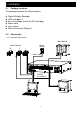
2. Installation 2.1 Package contents The package contents the following items. l l l l l l Digital Multiplex Recorder HDD cartridge x 2 Key for cartridge (Inside of HDD cartridge) Power cord User manual Rack mounting kit (Optional) 2.2 Connection 2.2.1 Connect with cameras Main Monitor Alarm Sensor Video Camera 16 .. . . 2 1 .. . .
2.
2.4 RS232 Remote Protocol You can use the PC keyboard to simulate DMR keypad.
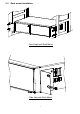
3. Configuration 3.1 Install HDD 3.1.1 Installing Hard Drive into Cartridge 3.1.1.1. Pull the handle outwards to remove the carrier body away from the cartridge frame. 3.1.1.2. Push the open button to slide the top cover backwards and remove. 3.1.1.3. Inside can be found the keys and fixing screws. 3.1.1.4. Insert the DC power cable and IDE cable on the HDD. 3.1.1.5. Position the HDD into carrier body and secure the HDD with the four 6#-32 screws provided. 3.1.1.6.
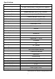
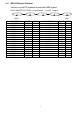
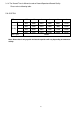
3.1.4 The Record Time is different based on Record Speed and Record Quality. Please refer to following table. PAL SYSTEM IPS Best Record High Quality Normal Basic 12A 12 6 3 2 1 48hr 100hr 202hr 406hr 608hr 1216hr 60hr 126hr 254hr 506hr 760hr 1520hr 98hr 202hr 406hr 810hr 1216hr 2440hr 162hr 336hr 676hr 1350hr 2026hr 4050hr HDD Type 240GB Note: Above data is only a guide and actual capacities will vary depending on amount of activity.
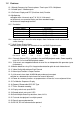
Front panel keypad 1 3 5 7 9 11 13 15 AVC 777 Digital Multiplex Recorder 2 4 6 8 10 12 14 Up 16 Left MENU ENTER ZOOM SLOW HDD SELECT Right REC HDD Full ALARM TIMER PLAY POWER REC Down Please follow the instructions below to operate this unit. 1. Install HDD This unit comes with two removable hard disk drive trays. Before turning on this device, you must install at least one hard disk drive (not including in standard package), and make it ready to operate.
(3) ALARM: When Alarm Enable : Yes (when the alarm is triggered, the led is flashing) (4) TIMER: When Timer Enable : Yes (5) PLAY: Play operation (6) REC: Recording operation 12. CAMERA (1-16) : Press the Camera Select (1-16) to select the required camera 13. REC : Press REC to start recording. 14. REW / Left : REW : Under DMR play mode, it can play video backward at high speed, and press REW again to adjust speed from 1, 2, 4, 8, 16, 32 times Left : Under setup mode , it can work as Left button. 15.
3.3 Back panel connection MONITOR LOOP AUDIO IN INPUT CALL POWER RISK OF ELECTRIC SHOCK DO NOT OPEN EXTERNAL I/O WARNING : TO REDUCE THE RISK OF ELECTRIC SHOCK, DO NOT REMOVE COVER (OR BACK). NO USER-SERVICEABLE PARTS INSIDE. REFER SERVICING TO QUALIFIED SERVICEPERSONNEL. 3.3.1 Power input Please use the power provided adaptor. 3.3.2 External I/O Controlled remotely by an external device or control system. Alarm input / output. 3.3.3 75 / HI When using Loop through function, please switch to HI. 3.
3.3.
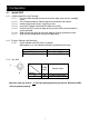
PIN 1. GND GROUND PIN 2. – PIN 9 , PIN 15 – PIN 22. ALARM INPUTS When a connection is made between an alarm input and to GND (PIN 1) on the D25 connector, the DMR will start recording and the buzzer will sound. When Menu/ Camera/ Alarm is set up to “Low”: When alarm input signal is “ Low ”, the unit starts to record and sounds buzzer. When Menu/ Camera/ Alarm is set up to “High”: When alarm input signal is “ High ”, the unit starts to record and sounds buzzer. PIN 10. NO Connection PIN 11/23.
3.4 Menu setup Press ”MENU” to enter main menu. A password is required to access main menu. Press “Right” “Left” to move digit, and Press ”Up” “Down” to select number. Press ”ENTER” button to confirm password. PASSWORD : 0000 Ex.: Password : 0000 (Default : 0000) After keying in the correct password and confirming by pressing ”ENTER” button, the screen will show the following options.
Press ”Up” “Down” to choose SYSTEM setup (Menu) SEARCH TIMER RECORD CAMERA ? SYSTEM EVENT SEARCH TIMER RECORD CAMERA ? SYSTEM EVENT Press ”ENTER” to confirm SYSTEM setup, and the screen will show the following options.
3.5.2 INT AUDIBLE ALARM setup: This setting allows the user to set the INTERNAL AUDIBLE ALARM. The alarm will be trigged by an event occurrence when the setting is ON. 3.5.2.1 Press ” Up” or “ Down” to choose INT AUDIBLE ALARM 3.5.2.2 Press ” ENTER” button to confirm INT AUDIBLE ALARM 3.5.2.3 Press ” Up” or “ Down” to choose the INT AUDIBLE ALARM : ON/OFF ON: Internal Buzzer ON OFF: Internal Buzzer OFF 3.5.2.4 Press ” MENU” to exit and confirm the current operation. 3.5.2.
3.5.5 DWELL TIME setup This setting allows the user to set the DWELL TIME. DWELL TIME is the length of time that each channel is sequentially shown on the CALL monitor output. 3.5.5.1 Press ” Up” or “ Down” to choose DWELL TIME setup. 3.5.5.2 Press ” ENTER” to confirm DWELL TIME setup. 3.5.5.3 Press ” Up” or “ Down” to choose DWELL TIME setup. 01~10 SEC. 3.5.5.4 Press ” MENU” to exit and confirm the current operation. 3.5.5.5 Press ” MENU” again to exit and close SYSTEM setup mode. 3.5.
3.5.8 TIME DISPLAY format setup This setting allows the user to set the time format on the monitor. 3.5.8.1 Press ” Up” or “ Down ” to choose TIME DISPLAY setup. 3.5.8.2 Press ” ENTER ” to confirm TIME DISPLAY setup. 3.5.8.3 Press” Up ” or “ Down ” to choose TIME DISPLAY setup. OFF, Y/M/D, M/D/Y, D/M/Y. 3.5.8.4 Press ” MENU ” to exit and confirm the current operation. 3.5.8.5 Press ” MENU ” again to exit and close SYSTEM setup mode. 3.5.9 TIME setup: This setting allows the user to set time on the monitor.
3.5.11 CLEAR HDD setup This setting allows the user to clear the HDD. 3.5.11.1 Press ” Up ” or “ Down ” to choose CLEAR HDD setup. 3.5.11.2 Press ” ENTER ” to confirm CLEAR HDD setup. 3.5.11.3 Press ” Up ” or “ Down ” to choose CLEAR HDD setup YES or NO. YES: Confirm to clear HDD, and screen will show the following; ALL DATA IN HDD WILL BE CLEARED ARE YOU SURE? (? : NO ? : YES ) Press“ ? ” to clear HDD NO: Confirm not to clear HDD. 3.5.11.4 Press ” MENU ” to exit and confirm the current operation. 3.5.11.
3.5.14 Remote protocol Baud Rate setup This setting allows the user to set the remote protocol baud rate. 3.5.14.1 Press ” Up ” or “ Down ” to choose Baud Rate setup. 3.5.14.2 Press ” ENTER ” to confirm 3.5.13.3 Press ” Up ” or “ Down ” to choose BAUD RATE setup 115200? 57600? 19200? 9600? 4800? 3600? 2400? 1200 3.5.14.4 Press ” MENU ” to exit and confirm the current operation. 3.5.14.5 Press ” MENU ” again to exit and close SYSTEM setup mode. 3.5.
3.6.1 LAST RECORD for recorded video Press ” Up ” or “ Down ” to choose LAST RECORD item. The following screen will be displayed. Press “ENTER” to confirm LAST RECORD. ? LAST RECORD FULL LIST ALARM LIST TIME SEARCH 3.6.2 FULL LIST for recorded video Press ” Up ” or “ Down ” to choose Full List item. The following screen will be displayed. ? Press “ ENTER ” to confirm Full List, and the LAST RECORD FULL LIST ALARM LIST TIME SEARCH ? M 2002-JAN-01 01:02:03 M-HDD following screen will be displayed.
3.6.3 ALARM LIST for recorded video Press ” Up ” or “ Down ” to choose ALARM LIST. The following screen will be displayed. ? Press “ENTER” to confirm FULL LIST, and the following screen will be displayed. Press ” Up ” or “ Down ” to choose the desired recorded event (There will only be eight shown on one page.), and press “ Left ” or “ Right” to change the pages.
3.7 TIMER setup (Schedule Time-Lapse record mode setup ) 3.7.1 Enter TIMER setup Press ”MENU” to enter the main menu. It is necessary to enter the password to access the main menu. Press “ Left ” or “Right ” to move digit, and press ” Up “ or “ Down ” to select number. Press ”ENTER” button to confirm password. PASSWORD : 0000 Ex.: PASSWORD : 0000 (Default : 0000) After keying in the correct password, and confirming by pressing ”ENTER” button, the following screen will be displayed.
3.7.2 TIMER setup: 3.7.2.1 Press ” ENTER ” to confirm TIMER setup. 3.7.2.2 Press ” Up ” or “ Down ” to choose the Timer Record day Daily : Everyday MON : Monday TUE : Tuesday WED : Wednesday THU : Thursday FRI : Friday SAT : Saturday SUN : Sunday MO-FR : Monday to Friday SA-SU : Saturday & Sunday JAN-01 : Special Date OFF : Not activated 3.7.2.3 Press “ Left ” or “ Right ” to move to START record time 00:00 (HH:MM) Press ” Up ” or “ Down ” to change START record time numerical digit 3.7.2.
3.8 RECORD MODE setup 3.8.1 To Enter “ Record “ setup Press ”MENU” to enter the main menu. It is necessary to enter the password to access the main menu. Press “ Left ” or “ Right ” to move digit, and press ” Up ” or “ Down ” to select number. Press ” ENTER ” button to confirm password. PASSWORD: 0000 Ex.: PASSWORD: 0000 (Default: 0000) After keying in the correct password, and confirming by pressing ” ENTER ” button, the following screen will be displayed.
3.8.2 HDD OVERWRITE setup : 3.8.2.1 Press ” ENTER” to confirm HDD OVERWRITE setup. 3.8.2.2 Press ” Up ” or “ Down ” to choose HDD OVERWRITE. NO : When HDD is full it will stop recording YES : When HDD is full it will overwrite the HDD recording 3.8.2.3 Press ” MENU ” to exit and confirm the current operation. 3.8.2.4 Press again ” MENU ” to exit and close HDD OVERWRITE setup mode. 3.8.3 RECORD IPS setup: 3.8.3.1 Press ” ENTER” to confirm RECORD IPS setup. 3.8.3.
3.9 CAMERA setup Press ”MENU” to enter main menu. It is necessary to enter password to access the main menu. Press “ Left ” or “ Right ” to move digit, and to press ” Up ” or “ Down ” to select number. Press ” ENTER ” button to confirm password. PASSWORD : 0000 Ex.: Password : 0000 (Default : 0000) After keying in the correct password, and confirming by pressing ” ENTER ” button, Following screen will be displayed.
3.9.1 TITLE :It allows assignment of a title to each camera input. Initially each title is the camera’s number 01 -16 3.9.1.1 Press” Up ” or “ Down ” : Select channel in the Channel setup 3.9.1.2 Press ENTER: Confirm the channel 3.9.1.3 Press “ Left ” or “ Right ” : Select the location of title (6 characters maximum) 3.9.1.4 Press ” Up ” or “ Down ” : Select the characters for display (0~9, A~Z,-, :, (, ), ) 3.9.1.5 Press “ MENU ” : Confirm and exit the title setting 3.9.1.
3.9.5 RECORD 3.9.5.1 Press ” Up ” or “ Down ” : Select channel in the Channel setup 3.9.5.2 Press “ENTER” : Enter the channel setup 3.9.5.3 Press ” “ Left ” or “ Right ” : Select Record on the screen. 3.9.5.4 Press ” Up ” or “ Down ” : Select DMR record method as below (DMR will only record the channel which has been set up for EVENT/ NORMAL/ OFF) EVENT : when alarm input is triggered, the DMR will record the alarming channel more frequently. For example : the DMR normal record method is 1-2-3-4-5-……-16.
3.10.4 Press “ SLOW “ button to setup the Sensitivity list up to 255 Press “ REC “ button to setup the Sensitivity list down to 000 Sensitivity value is related to motion and brightness change. Low value (as 001) means higher sensitivity on motion and brightness change. High value (as 255) means lower sensitivity on motion and brightness change. User can choose the suitable sensitivity value in different locations. The default value is set on 32.
Figure 1-1 MOTION DETECTION SETUP – 1~16 1 4 2 3 5 6 7 8 9 10 11 12 13 14 15 032 -- -- -- -- -- -- -- -- -- -- -- -- Figure 1-2 MOTION DETECTION SETUP – LINE 1 4 2 3 5 6 7 8 9 10 11 12 -- 13 -- 14 -- 15 032 -- -- -- Figure 1-3 1 2 -- -- -- -- -- -- -- -- -- -- -- -- MOTION DETECTION SETUP – ALL 3 4 5 6 7 8 9 10 11 12 13 14 15 032 -- -- -- -- -- -- -- -- -- 33 -- -- -- -- -- --
3.11 Event 3.11.1 Enter “ Event “ list Press ”MENU” to enter main menu. It is necessary to enter the password to access the main menu. Press “ Left ” or “ Right ” to move digit, and to press” Up ” or “ Down ” to select number. To press ”ENTER” button to confirm password. PASSWORD : 0000 Ex.: Password: 0000 (Default: 0000) After keying in the correct password, and confirming by pressing ”ENTER” button, The following screen will be displayed.
4. Operation 4.1 Power on Before turning on the power, make sure the HDD has been locked, and the POWER LED is red. After pressing the POWER button, the POWER LED will turn to orange colo ur, then all other LED lights will turn to RED colo ur except the LED for the HDD. OSD screen will display “HDD Detecting”, Power on period will take approximately 15 to 20 seconds. The screen will then show HDD Master and Slave connected. After setup period of DMR the POWER LED will turn to green colour.
4.2.2 Timer Record DMR will follow Timer setup to record, and the recording speed and quality will be as the timer recording mode setup in main menu. The screen will be as displayed on the right. T : Timer record OW : HDD Over Write 032GB : If the OW location shows 32GB, it means that 32 GB HDD left for video recording. (1 HDD installed) 001GB : If the OW location shows 32GB, it means 032GB that 32 GB left in slave HDD and 1 GB left in master HDD for video recording.
4.5 Picture in Picture (PIP) Press PIP button to enter PIP display screen. The PIP format displays a full screen “background” picture with a 1/16 size screen ‘insert”. 4.5.1 Press button to display the last selected PIP mode. ID - the camera numbers appear on the bottom of the screen 4.5.2 To change the selection press SELECT. When the camera ID flashes a new camera can be selected by pressing the individual camera button. This applies to both the main picture and the insert. 4.5.
slow rewind speed 1/2X, and press twice “? ? ” speed for 1/4X, ….the minimum slow speed can be 1/32X. 4.7.3 Pause : Press “ PLAY ” then press “ PAUSE ”, it will pause the screen 4.7.4 Stop : Press “ STOP ” under any circumstance, it will return DMR to live monitoring mode. 4.7.5 Image jog dial 4.7.5.1 Press “ PLAY ” then press “ PAUSE ”, it will pause the screen. Then press “? ? ” for single image play, it will show the recorded image one by one when continuously pressing the ” ? ? ”. 4.7.5.
5. Trouble shooting & Appendix 5.1 Trouble shooting When DMR appears to malfunction; it may be not serious and can be corrected. The table below describes some typical problems and their remedies. Check them before calling your DMR dealer: PROBLEM HDD Not Found REMEDY l Please Insert HDD l Please use the Key to lock the HDD Cartridge And press any key No power Not working when press any button l Check power cord connections. l Confirm that there is power at the outlet.
5.