® DiamondMax Plus 40 54098U8, 53073U6, 52049U4, 51536U3, 51024U2 Part #1429/A All material contained herein Copyright © 2000 Maxtor Corporation. MaxFax™ is a trademark of Maxtor Corporation. DiamondMax ®, Maxtor ® and No Quibble ® Service are registered trademarks of Maxtor Corporation. Other brands or products are trademarks or registered trademarks of their respective holders. Contents and specifications subject to change without notice. All rights reserved.
Before Y ou Begin You Thank you for your interest in the Maxtor DiamondMax® Plus 40 AT hard disk drives. This manual provides technical information for OEM engineers and systems integrators regarding the installation and use of DiamondMax hard drives. Drive repair should be performed only at an authorized repair center. For repair information, contact the Maxtor Customer Service Center at 800-2MAXTOR or 408-922-2085. Before unpacking the hard drive, please review Sections 1 through 4.
DIAMONDMAX PLUS 40 PRODUCT MANUAL Contents Section 1 — Introduction Maxtor Corporation Products Support Manual Organization Abbreviations Conventions Key Words Numbering Signal Conventions 1-1 1-1 1-1 1-1 1-1 1-2 1-2 1-2 1-2 Section 2 — Product Description The DiamondMax® Plus 40 Product Features Functional/Interface Zone Density Recording Read/Write Multiple Mode UltraDMA - Mode 4 Multi-word DMA (EISA Type B) - Mode 2 Sector Address Translation Logical Block Addressing Defect Management Zone On-the-Fly
DIAMONDMAX PLUS 40 PRODUCT MANUAL Section 3 — Product Specifications Models and Capacities Drive Configuration Performance Specifications Physical Dimensions Power Requirements Power Mode Definitions Spin-up Seek Read/Write Idle Standby Sleep EPA Energy Star Compliance Environmental Limits Shock and Vibration Reliability Specifications Annual Return Rate Quality Acceptance Rate Start/Stop Cycles Data Reliability Component Design Life EMC/EMI EMC Compliance Canadian Emissions Statement Safety Regulatory Com
DIAMONDMAX PLUS 40 PRODUCT MANUAL Section 5 — AT Interface Description Interface Connector Pin Description Summary Pin Description Table PIO Timing DMA Timing Ultra DMA Timing Parameters 5-1 5-1 5-2 5-3 5-4 5-5 Section 6 — Host Software Interface Task File Registers Data Register Error Register Features Register Sector Count Register Sector Number Register Cylinder Number Registers Device/Head Register Status Register Command Register Read Commands Write Commands Mode Set/Check Commands Power Mode Comman
DIAMONDMAX PLUS 40 PRODUCT MANUAL Write Verify Sector(s) Write Sector Buffer Write DMA Write Multiple Ultra DMA Set Feature Commands Set Features Mode Power Mode Commands Standby Immediate Idle Immediate Standby Idle Check Power Mode Set Sleep Mode Default Power-on Condition Initialization Commands Identify Drive Initialize Drive Parameters Seek, Format, and Diagnostic Commands S.M.A.R.T.
DIAMONDMAX PLUS 40 PRODUCT MANUAL Figures Figure Title Page 2-1 3-1 4-1 4-2 4-3 4-4 4-5 4-6 4-7 5-1 5-2 5-3 5-4 5-5 5-6 5-7 5-8 5-9 5 - 10 5 - 11 5 - 12 5 - 13 PCBA Jumper Location and Configuration Outline and Mounting Dimensions Multi-pack Shipping Container Single-pack Shipping Container (Option A) Single-pack Shipping Container (Option B) Master, Slave and Cable Select Settings 5.
DIAMONDMAX PLUS 40 – INTRODUCTION SECTION 1 Introduction Maxtor Corporation Maxtor Corporation has been providing high-quality computer storage products since 1982. Along the way, we’ve seen many changes in data storage needs. Not long ago, only a handful of specific users needed more than a couple hundred megabytes of storage. Today, downloading from the Internet and CD-ROMs, multimedia, networking and advanced office applications are driving storage needs even higher.
DIAMONDMAX PLUS 40 – INTRODUCTION Conventions If there is a conflict between text and tables, the table shall be accepted as being correct. Key Words The names of abbreviations, commands, fields and acronyms used as signal names are in all uppercase type (e.g., IDENTIFY DRIVE). Fields containing only one bit are usually referred to as the “name” bit instead of the “name” field. Names of drive registers begin with a capital letter (e.g., Cylinder High register).
PRODUCT DESCRIPTION SECTION 2 Product Description Maxtor DiamondMax® Plus 40 AT disk drives are 1-inch high, 3.5-inch diameter random access storage devices which incorporate an on-board ATA-5/Ultra DMA 66 controller. High capacity is achieved by a balanced combination of high areal recording density and the latest data encoding and servo techniques. Maxtor's latest advancements in electronic packaging and integration methods have lowered the drive's power consumption and increased its reliability.
PRODUCT DESCRIPTION Product Features Functional / Interface Maxtor DiamondMax Plus 40 hard drives contain all necessary mechanical and electronic parts to interpret control signals and commands from an AT-compatible host computer. See Section 3 Product Specifications, for complete drive specifications. Zone Density Recording The disk capacity is increased with bit density management – common with Zone Density Recording. Each disk surface is divided into 16 circumferential zones.
PRODUCT DESCRIPTION The LBA is checked for violating the drive capacity. If it does not, the LBA is converted to physical drive cylinder, head and sector values. The physical address is then used to access or store the data on the disk and for other drive related operations. Defect Management Zone (DMZ) Each drive model has a fixed number of spare sectors per drive, all of which are located at the end of the drive.
PRODUCT DESCRIPTION Major HDA Components Drive Mechanism A brush-less DC direct drive motor rotates the spindle at 7,200 RPM (±0.1%). The dynamically balanced motor/spindle assembly ensures minimal mechanical run-out to the disks. A dynamic brake provides a fast stop to the spindle motor upon power removal. The speed tolerance includes motor performance and motor circuit tolerances.
PRODUCT DESCRIPTION Subsystem Configuration Dual Drive Support Two drives may be accessed via a common interface cable, using the same range of I/O addresses. The drives are jumpered as device 0 or 1 (Master/Slave), and are selected by the drive select bit in the Device/Head register of the task file. All Task File registers are written in parallel to both drives.
PRODUCT SPECIFICATIONS SECTION 3 Product Specifications Models and Capacities MODEL Formatted Capacity (MB LBA Mode) 54098U8 53073U6 52049U4 51536U3 51024U2 40,980 30,735 20,490 15,367 10,245 Maxtor defines one megabyte as 106 or one million bytes and one gigabyte as 109 or one billion bytes.
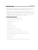
PRODUCT SPECIFICATIONS Physical Dimensions (maximum) PARAMETER Height Length Width Weight STANDARD 1.028 inches 5.787 inches 4.00 inches 1.3 pounds METRIC 26.1 millimeters 147 millimeters 101.6 millimeters 0.59 kilograms 1.028 max [26.1 mm max 6 x 6-32 UNC -28 THREAD 1.638 ± .010 [41.6 ± 0.25 mm] 1.122 ± .020 [28.5 ± 0.5 mm] .25 ± .01 [6.35 ± 0.25 mm 4.00 ± .01 [101.6 ± 0.5 mm] 5.787 max [147 mm max] 1.625 ± .02 [41.28 ± 0.5 mm] 4.00 ± .01 [101.6 ± 0.25 mm] 1.75 ± .01 [44.95 ± 0.25 mm] 3.75 ± .
PRODUCT SPECIFICATIONS Power Requirements MODE 12V ± 10% 5V ± 5% Spin-up (peak) 250 0 mA 620 mA Seek (avg) 80 0 mA 510 mA P OW E R 12.9 W Read/Write (avg) 350 mA 530 mA 6.8 W Idle (avg) 350 mA 490 mA 6.6 W St andby (avg) 15 mA 235 mA 1.4 W Sleep (avg) 15 mA 170 mA 1.0 W Power Mode Definitions Spin-up The drive is spinning up following initial application of power and has not yet reached full speed. Seek A random access operation by the disk drive.
PRODUCT SPECIFICATIONS Shock and Vibration PARAMETER OPERATING NON-OPERATING Mechanical Shock Rotational Shock Random Vibration 60 Gs, 2.0 ms, no errors 250 Gs, 2.0 ms, no damage 20,000 Rad/sec,0.5 - 1.0 ms, no damage 10 Hz at 0.05 G2/Hz 20 Hz at 0.055 G2/Hz 300 Hz at 0.05 G2/Hz 301 Hz at 0.0014 G2/Hz 500 - 760 Hz at 0.001 G2/Hz 877 Hz at 0.003 G2/Hz 1000 - 1570 Hz at 0.001 G2/Hz 2000 Hz at 0.001 G2/Hz Swept Sine Vibration 10 - 300 Hz 10 - 45 Hz at 0.004 G2/Hz 48 - 62 Hz at 0.
PRODUCT SPECIFICATIONS EMC/EMI Radiated Electromagnetic Field Emissions - EMC Compliance The hard disk drive mechanism is designed as a subassembly for installation into a suitable enclosure and is therefore not subject to Subpart J of Part 15 of FCC Rules (47CFR15) or the Canadian Department of Communications Radio Interference Regulations.
INSTALLATION SECTION 4 Handling and Installation Hard Drive Handling Precautions ◆ If the handling precautions are not followed, damage to the hard drive may result - which may void the warranty. ◆ During handling, NEVER drop, jar, or bump a drive. Handle the drive by its sides and avoid touching the printed circuit board assembly (PCBA). ◆ Hard drives are sensitive to electrostatic discharge (ESD) damage.
INSTALLATION Unpacking and Inspection Retain any packing material for reuse. Inspect the shipping container for evidence of damage in transit. Notify the carrier immediately in case of damage to the shipping container. As they are removed, inspect drives for evidence of shipping damage or loose hardware. If a drive is damaged (and no container damage is evident), notify Maxtor immediately for drive disposition.
INSTALLATION Figure 4 - 2 Single Pack Shipping Container (Option A) Figure 4 - 3 Single Pack Shipping Container (Option B) Repacking If a Maxtor drive requires return, repack it using Maxtor packing materials, including the antistatic bag. Physical Installation Recommended Mounting Configuration The DiamondMax® drive design allows greater shock tolerance than that afforded by larger, heavier drives.
INSTALLATION Before You Begin Important – Please Read Please read this installation section completely before installing the Maxtor hard drive. It gives general information for installing a Maxtor hard drive in a typical computer system. If you don’t understand the installation steps, have a qualified computer technician install the hard drive. Back up. Protect your Existing Data Periodic backup of important data is always a good idea.
INSTALLATION Install the Hard Drive in a Device Bay Refer to your computer user’s manual for specific mounting information. Be sure to secure the drive to the device bay with all four screws. Attach the Interface and Power Cables Do not force or rock the connectors into their sockets on the hard drive. Push them in straight until they are seated. Note: DiamondMax Hard Drive Kits that carry a “U” in the kit number are UltraDMA 66 compatible hard drives.
AT INTERFACE DESCRIPTION SECTION 5 AT Interface Description Interface Connector All DiamondMax® Plus 40 AT drives have a 40-pin ATA interface connector mounted on the PCBA. The drive may connect directly to the host; or it can also accommodate a cable connection (maximum cable length: 18 inches).
AT INTERFACE DESCRIPTION Pin Description Table P IN N A M E P IN I/ O RESET - 01 I DD0 17 I/O I/O S IG N A L N A M E SIGNAL DESCRIPTION Host Reset Reset signal from the host system. Active during power up and inactive after. H o st D at a B u s 16 bit bi-directional data bus between host and drive. Lower 8 bits used for register and ECC byte transfers. All 16 bits used for data transfers.
AT INTERFACE DESCRIPTION PIO Timing M ODE 0 M ODE 1 M ODE 2 M ODE 3 M ODE 4 t0 TIMING PARAMETERS Cycle Time (min) 60 0 ns 383 ns 240 ns 180 ns 120 ns t1 Address valid to DIOR-/DIOW- setup (min) 70 ns 50 ns 30 ns 30 ns 25 ns t2 DIOR-/DIOW- 16-bit (min) 165 ns 125 ns 100 ns 80 ns 70 ns t2 i DIOR-/DIOW- recover y time (min) 70 ns 25 ns t3 DIOW- data setup (min) 60 ns 45 ns 30 ns 30 ns 20 ns t4 DIOW- data hold (min) 30 ns 20 ns 15 ns 10 ns 10 ns t5 DIOR- data setup
AT INTERFACE DESCRIPTION DMA Timing TIMING PARAMETERS M ODE 0 M ODE 1 M ODE 2 480 ns 150 ns 120 ns DIOR-/DIOW- (min) 215 ns 80 ns 70 ns D IO R - d a t a a c c e s s (m in ) 150 ns 60 ns t0 Cycle Time (min) tC DMACK to DMARQ delay tD tE tF D IO R - d a t a h o ld (m in ) 5 ns 5 ns 5 ns tG DIOR-/DIOW- data setup (min) 100 ns 30 ns 20 ns tH DIOW- data hold (min) 20 ns 15 ns 10 ns tI DMACK to DIOR-/DIOW- setup (min) 0 0 0 tJ DIOR-/DIOW- to DMACK hold (min) 20 ns 5 ns 5
AT INTERFACE DESCRIPTION Ultra DMA Timing TIMING PARAMETERS (all times in nanoseconds) M ODE 0 M IN M AX M ODE 1 M IN M AX M ODE 2 M IN M AX M ODE 3 M IN M AX M ODE 4 M IN tCYC Cycle Time (from STROBE edge to STROBE edge) 112 73 54 39 25 t2CYC Two cycle time (from rising edge to next rising edge or from falling edge to next falling edge of STROBE) 230 154 115 86 57 M AX tDS Data setup time (at recipient) 15 10 7 7 5 tDH D a t a h o ld t im e (a t r e c ip ie n t ) 5 5 5
AT INTERFACE DESCRIPTION t2CYC tCYC tCYC t2CYC DSTROBE at device tDVH tDVS tDVH tDVS tDVH DD(15:0) at device DSTROBE at host tDH tDS tDH tDS DD(15:0) at host Figure 5 - 5 Sustained Ultra DMA Data In Burst DMARQ (device) DMACK(host) tRP STOP (host) tSR HDMARDY(host) tRFS DSTROBE (device) DD(15:0) (device) Figure 5 - 6 Host Pausing an Ultra DMA Data In Burst 5–6 tDH
AT INTERFACE DESCRIPTION DMARQ (device) tMLI DMACK(host) tACK tLI tLI STOP (host) tACK tLI HDMARDY(host) tSS tIORDYZ DSTROBE (device) tZAH tAZ tDVS DD(15:0) tDVH CRC tACK DA0, DA1, DA2, CS0-, CS1- Figure 5 - 7 Device Terminating an Ultra DMA Data In Burst DMARQ (device) tLI tMLI DMACK(host) tZAH tAZ tRP tACK STOP (host) tACK HDMARDY(host) tRFS tLI tMLI tIORDYZ DSTROBE (device) tDVS DD(15:0) tDVH CRC tACK DA0, DA1, DA2, CS0-, CS1- Figure 5 - 8 Host Terminating an Ultra DMA Data In
AT INTERFACE DESCRIPTION DMARQ (device) tUI DMACK(host) tACK tENV STOP (host) tZIORDY tLI tUI DDMARDY(device) tACK HSTROBE (host) tDVS tDVH DD(15:0) (host) tACK DA0, DA1, DA2, CS0-, CS1- Figure 5 - 9 Initiating an Ultra DMA Data Out Burst t2CYC tCYC tCYC t2CYC HSTROBE at host tDVH tDVS tDVH tDVS tDVH DD(15:0) at host HSTROBE at device tDH tDS tDH tDS DD(15:0) at device Figure 5 - 10 Sustained Ultra DMA Data Out Burst 5–8 tDH
AT INTERFACE DESCRIPTION tRP DMARQ (device) DMACK(host) STOP (host) tSR DDMARDY(device) tRFS HSTROBE (host) DD(15:0) (host) Figure 5 - 11 Device Pausing an Ultra DMA Data Out Burst tLI DMARQ (device) tMLI DMACK(host) tLI tSS tACK STOP (host) tLI tIORDYZ DDMARDY(device) tACK HSTROBE (host) tDVS DD(15:0) (host) tDVH CRC tACK DA0, DA1, DA2, CS0-, CS1- Figure 5 - 12 Host Terminating an Ultra DMA Data Out Burst 5–9
AT INTERFACE DESCRIPTION DMARQ (device) DMACK(host) tLI tMLI tACK STOP (host) tRP tIORDYZ DDMARDY(device) tRFS tLI tMLI tACK HSTROBE (host) tDVS DD(15:0) (host) tDVH CRC tACK DA0, DA1, DA2, CS0-, CS1- Figure 5 - 13 Device Terminating an Ultra DMA Data Out Burst 5 – 10
HOST SOFTWARE INTERFACE SECTION 6 Host Software Interface The host communicates with the drive through a set of controller registers accessed via the host’s I/O ports. These registers divide into two groups: the Task File, used for passing commands and command parameters and the Control/Diagnostic registers. Task File Registers The Task File consists of eight registers used to control fixed disk operations.
HOST SOFTWARE INTERFACE Sector Count Register Holds the number of sectors to be sent during a Read or Write command, and the number of sectors per track during a Format command. A value of zero in this register implies a transfer of 256 sectors. A multisector operation decrements the Sector Count register. If an error occurs during such an operation, this register contains the remaining number of sectors to be transferred. Sector Number Register Holds the starting sector number for any disk operation.
HOST SOFTWARE INTERFACE Command Register Contains code for the command to be performed. Additional command information should be written to the task file before the Command register is loaded. When this register is written, the BUSY bit in the Status register sets, and interrupt request to the host clears; invalid commands abort. (Detailed information on interface commands is given in Section 7.
HOST SOFTWARE INTERFACE Summary CO M M A N D N A M E PARAMETERS U S ED b7 b6 b5 b4 b3 b2 b1 b0 F SC SN C S DH Recalibrate 0 0 0 1 x x x x N N N N D Y Read Sector(s) 0 0 1 0 0 0 L x N Y Y Y Read DMA 1 1 0 0 1 0 0 x N Y Y Y Y Write Sector(s) 0 0 1 1 0 0 L x N Y Y Y Y Write DMA 1 1 0 0 1 0 1 x N Y Y Y Y Write Verify Sector(s) 0 0 1 1 1 1 0 0 N Y Y Y Y Y Read Verify Sector(s) 0 1 0 0 0 0 0 x N Y Y Y F
HOST SOFTWARE INTERFACE Control Diagnostic Registers These I/O port addresses reference three Control/Diagnostic registers: I/O PORT REA D W R IT E 3F6h Alternate Status Fixed Disk Control 3F7h D ig it a l In p u t N o t u se d Alternate Status Register Contains the same information as the Status register in the Task File. However, this register may be read at any time without clearing a pending interrupt.
HOST SOFTWARE INTERFACE Reset and Interrupt Handling Reset Handling One of three different conditions may cause a reset: power on, hardware reset or software reset. All three cause the interface processor to initialize itself and the Task File registers of the interface. A reset also causes a set of the Busy bit in the Status register. The Busy bit does not clear until the reset clears and the drive completes initialization. Completion of a reset operation does not generate a host interrupt.
INTERFACE COMMANDS SECTION 7 Interface Commands The following section describes the commands (and any parameters necessary to execute them), as well as Status and Error register bits affected.
INTERFACE COMMANDS Read Commands Read Sector(s) Reads from 1 to 256 sectors, as specified in the Command Block, beginning at the specified sector. (A sector count of 0 requests 256 sectors.) Immediately after the Command register is written, the drive sets the BSY bit and begins execution of the command. If the drive is not already on the desired track, an implied seek is performed. Once at the desired track, the drive searches for the data address mark of the requested sector.
INTERFACE COMMANDS Read DMA Multi-word DMA Identical to the Read Sector(s) command, except that 1. The host initializes a slave-DMA channel prior to issuing the command, 2. Data transfers are qualified by DMARQ and are performed by the slave-DMA channel and 3. The drive issues only one interrupt per command to indicate that data transfer has terminated and status is available.
INTERFACE COMMANDS Set Multiple Mode Enables the controller to perform Read and Write Multiple operations, and establishes the block count for these commands. Before issuing this command, the Sector Count register should be loaded with the number of sectors per block. The drives support block sizes of 2, 4, 8 and 16 sectors. When this command is received, the controller sets BSY and examines the Sector Count register contents.
INTERFACE COMMANDS Write Multiple Performs similarly to the Write Sector(s) command, except that: 1. The controller sets BSY immediately upon receipt of the command, 2. Data transfers are multiple sector blocks and 3. The Long bit and Retry bit is not valid. Command execution differs from Write Sector(s) because: 1. Several sectors transfer to the host as a block without intervening interrupts. 2. DRQ qualification of the transfer is required at the start of the block, not on each sector.
INTERFACE COMMANDS Set Feature Commands Set Features Mode Enables or disables features supported by the drive. When the drive receives this command it: 1. 2. 3. 4. Sets BSY, Checks the contents of the Features register, Clears BSY and Generates an interrupt. If the value of the register is not a feature supported by the drive, the command is aborted.
INTERFACE COMMANDS Power Mode Commands Standby Immediate – 94h/E0h Spin down and do not change time out value. This command will spin the drive down and cause the drive to enter the STANDBY MODE immediately. If the drive is already spun down, the spin down sequence is not executed. Idle Immediate – 95h/E1h Spin up and do not change time out value. This command will spin up the spin motor if the drive is spun down, and cause the drive to enter the IDLE MODE immediately.
INTERFACE COMMANDS When enabling the Automatic Power Down sequence, the value placed in the Sector Count register is multiplied by five seconds to obtain the Time-out Interval value. If no drive commands are received from the host within the Time-out Interval, the drive automatically enters the STANDBY mode. The minimum value is 5 seconds.
INTERFACE COMMANDS Initialization Commands Identify Drive Allows the host to receive parameter information from the drive. When the command is received, the drive: 1. 2. 3. 4. Sets BSY, Stores the required parameter information in the sector buffer, Sets the DRQ bit and Generates an interrupt. The host may then read the information out of the sector buffer. Parameter words in the buffer follow. Note that all reserved bits or words should be zeroes.
INTERFACE COMMANDS WO RD 50 51 52 53 54 55 56 57 - 58 59 60 - 61 62 63 64 65 66 67 68 69-79 80 81 82 C O N T E N T D E S C R IP T IO N Re s e r ve d 15-8 = PIO dat a transfer mode 7-0 = not used 15-8 = DMA dat a transfer mode 7-0 = not used 15 = reser ved 2 , 1 = t h e f i e l d s s u p p o r t e d i n w o r d s 8 8 a r e va l i d , 0 = t h e f i e l d s s u p p o r t e d i n w o r d s 8 8 a r e n o t va l i d 1 , 1 = t h e f i e l d s r e p o r t s i n w o r d s 6 4 - 7 0 a r e va l i d , 0 = t h e f
INTERFACE COMMANDS WO R D 83 C O N T E N T D E S C R IP T IO N Command sets supported. If words 82, 83 and 84 = 0000h or FFFFh command set notification not s u p p o rte d . 15 = shall be cleared to zero 14 = shall be set to one 13-1 = reser ved 0, 1 = supports Download Microcode command 84 Command set extensions supported. If words 84, 85 and 86 = 0000h or FFFFh command set n o t if ic a t io n n o t s u p p o r t e d .
INTERFACE COMMANDS Initialize Drive Parameters Enables the drive to operate as any logical drive type. The drive will always be in the translate mode because of Zone Density Recording, which varies the number of sectors per track depending on the zone. Through setting the Sector Count Register and Drive Head Register, this command lets the host alter the drive's logical configuration. As a result, the drive can operate as any equal to or less than capacity drive type.
INTERFACE COMMANDS Seek, Format and Diagnostic Commands Seek Initiates a seek to the track, and selects the head specified in the Command block. 1. 2. 3. 4. Sets BSY in the Status register, Initiates the Seek, Resets BSY and Generates an interrupt. The drive does not wait for the seek to complete before returning the interrupt. If a new command is issued to a drive during the execution of a Seek command, the drive will wait (with BSY active) for the Seek to complete before executing the new command.
INTERFACE COMMANDS S.M.A.R.T. Command Set Execute S.M.A.R.T. The Self-Monitoring Analysis and Reporting Technology (S.M.A.R.T.) command has been implemented to improve the data integrity and data availability of hard disk drives. In some cases, a S.M.A.R.T. capable device will predict an impending failure with sufficient time to allow users to backup their data and replace the drive before data loss or loss of service. The S.M.A.R.T. sub-commands (listed below) comprise the ATA S.M.A.R.T.
SERVICE AND SUPPORT SECTION 8 Service and Support Service Policy If a customer discovers a defect in a DiamondMax® Plus 40 drive, Maxtor will, at its option, repair or replace the disk drive at no charge to the customer, provided it is returned during the warranty period. Drives must be properly packaged in Maxtor packaging or Maxtor-approved packaging to obtain warranty service. Any unauthorized repairs or adjustments to the drive void the warranty.
SERVICE AND SUPPORT MaxFax™ Service Use a touch-tone phone to order Technical Reference Sheets, Drive Specifications, Installation Sheets and other documents from our 24-hour automated fax retrieval system. Requested items are sent to your fax machine. U.S. and Canada Phone Outside U.S.
GLOSSARY GLOSSARY Glossary A BPI Acronym for bits per inch. See bit density. BLOCK ACCESS To obtain data from, or place data into, RAM, a register, or data storage device. A group of bytes handled, stored, and accessed as a logical data unit, such as an individual file record. BUFFER ACCESS TIME The interval between the issuing of an access command and the instant that the target data may be read or written. Access time includes seek time, latency and controller overhead time.
GLOSSARY CONTROLLER DIGITALMAGNETICRECORDING A miniature CPU dedicated to controlling a peripheral device, such as a disk drive, tape drive, video display terminal, or printer. The controller executes commands from the central processing unit and reissues commands to the peripheral device. See magnetic recording. CORRECTABLEERROR An error that can be overcome by the use of Error Detection and Correction.
GLOSSARY EXTRA PULSE HEAD DISK ASSEMBLY (HDA) Term used in surface certification. It is when a flux field discontinuity remains after the recording surface is erased, thereby producing an electrical output of a read head passing over the area with the discontinuity. An extra pulse occurs when the electrical output is larger than a specified threshold. The mechanical portion of a rigid, fixed disk drive. It usually includes disks, heads, spindle motor, and actuator.
GLOSSARY L LANDING ZONE OR LZONE The cylinder number to where ParkHeads move the read/write heads. LATE BIT A bit that is in the late half of the data window. MODIFIEDMODIFIEDFREQUENCYMODULATION(MMFM) A recording code similar to MFM that has a longer run length limited distance. MODULATION 1. Readback voltage fluctuation usually related to the rotational period of a disk. 2. A recording code, such as FM, MFM, or RLL, to translate between flux reversals and bits or bytes.
GLOSSARY PHASEMARGIN Measure in degrees of the amount of difference between excursions from the window center where flux reversals can occur and the edge of the data window. Similar to window margin. S SECTOR The smallest grouping of data on the hard disk; always 512 bytes. A logical segment of information on a particular track. The smallest addressable unit of storage on a disk. Tracks are made of sectors. PIO SECTOR PULSE SIGNAL PHYSICAL SECTOR Programmable Input Output.
GLOSSARY SOFTERROR UN-CORRECTABLEERROR A data error which can be overcome by rereading the data or repositioning the head. An error that is not able to be overcome with Error Detection and Correction. SOFT SECTORED UNFORMATTEDCAPACITY A technique where the controller determines the beginning of a sector by the reading of format information from the disk. This is contrasted to hard sectoring where a digital signal indicates the beginning of a sector on a track.