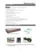
4 CH Digital Multiplex Recorder User Manual Please read this instructions thoroughly before operation and keep the manual in a safe place for further reference. 773 V 0.
DMR WARNING All the safety and operating instructions should be read before operation. The improper operation may cause permanent damage. • Please use the provided adaptor (Other adaptor is not suitable for this machine). • Please lift and place this equipment gently. • Do not expose this equipment to open sunlight. • Do not use this equipment near water or in contact with water. • Do not spill liquid of any kind on the equipment. • Please power down the unit before unplugging.
TABLE OF CONTENTS What do you get ? DMR • FEATURES ---------------------------------------------------------------- ------------------------ 3 • PACKAGE CONTENT ---------------------------------------------------------------- ---------- 3 Before Operation • INSTALLATION GUIDE ---------------------------------------------------------------- -------- 4 • FRONT PANEL ---------------------------------------------------------------- ------------------- 5 • BACK PANEL -------------------------------------
What do you get ? FEATURES DVR Features l Wavelet compression format replaces Time-Lapse VCR + Multiplexer / Quad l 4 audio inputs / 2 audio outputs l On Screen Display and Remote Control via Video Server & PC l Picture-in-picture (PIP) in live l Motion detection & motion trigger recording function l Alarm input & output function l Video loss detected on each channel l Linear Zoom (2x~4x) l Multiplexer & Quad recording mode switching l Recording rate up to full size 30 images/sec.
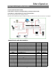
INSTALLATION GUIDE Before Operation 1. Connect cameras and monitor to the DVR. 2. Shown below is an example of connecting the DVR to your existing Observation System. 3. Install HDD (The compatible HDD Brands are listed in the following table.) Please refer to page.22 Appendix #1 for installation instructions. *The HDD must be installed before turning on the DMR, but if HDD is not installed, the DVR would be functioned as 4 CH multiplexer.
DMR FRONT PANEL 1. REMOVABLE HDD CARTRIDGE & KEYHOLE Please refer to page.22 Appendix #1. 2. LED LIGHT The LED Light is ON under following condition. • HDD : HDD status display • HDD Full : HDD is full • ALARM : To turn off the ALARM LED light, please refer to page.14 and set the ALARM mode as OFF. • TIMER : When Timer is set as Enabled • PLAY : On Playing mode • REC : On Recording mode 3. MENU Press MENU to enter main menu. 4. ENTER Press ENTER for confirmation. 5.
11. REC Press REC to start recording. 12. PLAY Press PLAY to playback recorded video. 13. PAUSE / Up • Pause : Under DMR play mode, it can pause the action. • UP : Under setup mode, it works as Up button. 14. STOP / Down • STOP : Under DMR Record / Play mode, it can stop the moment action. • DOWN : Under setup mode, it works as Down button. 15. REW / Left • REW : Under DMR play mode, it can play video backward at different speeds.
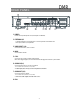
DMR REAR PANEL 1. P0WER Please use the provided power cord (The adaptor is embedded). 2. EXTERNAL I/O • Controlled remotely by an external device or control system like Video Web Server. • Alarm input, external I / O explanation. 3. VIDEO INPUT (1-4) Connect to video source, such as camera. 4. MAIN Connect to Main monitor. 5. CALL Connect to CALL monitor. Show the Switch Display. When alarm trigger happens, the call monitor will show the triggered channel for a period of time. 6.
Basic Operation GETTING STARTED Before using the DMR, please have a HDD installed ready, or it will be functioned as 4 CH multiplexer (refer to Appendix #1 for installation or removal of a HDD). 1. Connect the AC Power Cord and plug into an electrical outlet then press the power switch “ON”. The Red LED indicator light will be ON and the DMR is in Standby mode. 2. Press the Power button. The POWER LED will turn from red to orange, and other red LED indicators will turn ON.
PLAY BACK Press “ PLAY ” button, the DMR will show the last recording. 1. FAST FORWARD (F.F.) & FAST REWIND (F.R.) You can increase the speeds of Fast Forward and Rewind on the DMR. In the Play mode, press ” ► ” once to get 2X speed forward and press twice to get 4X speed,… and the maximum speed can reach 32X. Press ”◄ ” once to get 1X speed rewind and press twice to get 2X speed, … and the maximum speed can reach 32X. 2. SLOW FORWARD (S.F.) & SLOW REWIND (S.R.
Detailed Menu Setup MAIN MENU There are 12 options available in the Main Menu: (MENU) TIMER CAMERA RECORD ALARM DWELL PIP MOTION DISPLAY REMOTE USER SYSTEM EVENT TIMER ---------- Programs Specific Time to Record CAMERA ------- Camera Channel Setup RECORD ------- Record Mode Setup ALARM --------- Alarm Setup DWELL --------- Dwell time Setup PIP --------------- Picture in Picture Setup MOTION -------- Motion Detection Setup DISPLAY ------- Display Mode Setup REMOTE ------- Remote Control Setup USER --------
DMR MENU OPTIONS SYSTEM 1. AUDIO INPUT To choose one of 4 channels to record. ( It can only record 1 input) 2. BUZZER Set the BUZZER “ON”, it will buzzer by event occurrence when the setting is ON. 3. EXT ALARM To set the EXTERNAL AUDIBLE ALARM. It will be trigged by event occurrence when the setting is ON. 4. VLOSS ALARM To set the VLOSS ALARM. When the setting is “ON”, the alarm will occurrence by the setting of Buzzer, EXT alarm or Alarm Duration.
TIMER 1. DAY Select the day, or days of the week (Mon–Fri / Sat-Sun / Daily) that you wish to schedule the DMR to automatically record. NOTE : 1. Special Date could be changed by “ +” and “ -” buttons. 2. If you have selected the specific date and recording timer set from that specific day to a new day, then the Recording Timer Schedule will be set as whole week. For specific date of Recording Timer Schedule, it is not recommended to set End Time over 23:59.
CAMERA 1. TITLE (MENU) TIMER CAMERA RECORD ALARM DWELL PIP MOTION DISPLAY REMOTE USER SYSTEM EVENT Assign a title to each camera. Initially each title is the camera’s number. 2. ALARM Select LOW / OFF / HIGH for alarm polarity. The default value is LOW. TITLE ALARM REC BR CT CL HUE CAMERA 1 LOW ON 18 15 15 18 CAMERA 2 OFF OFF 18 15 15 18 CAMERA 3 HIGH OFF 18 15 15 18 CAMERA 4 HIGH ON 18 15 15 18 3. RECORD (REC) Set up which channel you want to record.
ALARM 1. ALARM ENABLE To set the ALARM ENABLE. It will be triggered by event occurrence when the setting is ON. 2. ALARM DURATION Set the reaction time which was determined by how long the alarm mode responded to a buzzer. Default setting is 10 sec. Options are 10 SEC, 15 SEC, 20 SEC, 30 SEC, 1 MIN, 2 MIN, 3 MIN, 5 MIN, 10 MIN, 15 MIN, 30 MIN, ALWAYS, AUTO. 3. REC IPS Select the images per second of recording during an ALARM.
MOTION 1. SEN (Sensitivity) Sets the sensitivity of the Pixel-based Motion Detection feature from 1fo 70. 2. MD-NVM Sets the number of targets in which Motion must occur in order to trigger an Alarm (from 1-99 target areas). Note: MD-NVM cannot be less than the number of targets set in the AREA. 3. RE Sets the Reference image to which the current screen is compared (from 1-99). For example, the value 64 would compare the current image to the 64th previous screen image.
7. DAY / START / END To setup the DAY and the START/ END time for motion trigger recording timer setting.
5. LOSS SCREEN Retain the last picture or select the LOSS SCREEN color. The options are GREEN, BLACK, BLUE. 6. OSD POSITION To set the OSD POSITION shown on monitor. (DISPLAY) TITLE DISPLAY OSD COLOR BORDER TYPE BORDER COLOR LOSS SCREEN OSD POSITION YES YELLOW 4/2 WHITE GREEN NORMAL The options are NORMAL or CENTER. REMOTE 1. REMOTE MODE Set the remote mode for connection with computer via RS-232 or RS-485. (Please refer to page. 23 for RS-232 Remote Control). 2.
EVENT A single page can display 16 recorded events. Press “◄ ” or “► ” to change the pages or press ▲ + ▼ to CLEAR the EVENT record.
OPERATION OPTIONS Advanced Operation ZOOM Press ZOOM button to enlarge the display of main picture. It displays zoomed picture on main picture and a small window inserted. The inserted window contains a movable 1/4 view size of the appointed camera. The range is from 2X to 4X. •Press PIP : Zoom in •Press QUAD : Zoom out •Press the “Zoom” button again to leave the zoom pointer. •Press Camera (1-4) to select channel. •Press ▲ ▼ ◄ ► to move the zoom position.
DMR KEY LOCK For advanced security, you can “Lock” the buttons on your DMR. Key-Lock prevents other people from using the system. Press ENTER and MENU at the same time to enable Key Lock. Press ENTER and MENU at the same time and key in password (Default : 0000), then press “ENTER“ to disable Key Lock. RS-232 REMOTE PROTOCOL You can use the PC keyboard to simulate DMR keypad.
DMR SPECIFICATIONS Video format Hard disk storage Record mode Camera Input Signal Camera Loop Back Main Monitor Output Call Monitor Output Audio input NTSC/EIA or PAL/CCIR IDE type, UDMA 66, supported 200 GB HDD Manual / Alarm / Timer / Motion Composite video signal 1 Vp-p 75Ω BNC, 4 channels Composite video signal 1 Vp-p 75Ω BNC, 4 channels Composite video signal 1 Vp-p 75Ω BNC Composite video signal 1 Vp-p 75Ω BNC 4 audio inputs, (RCA) * 2 audio outputs, (RCA) ** 16 * 12 targets per camera Audio output
APPENDIX #1 – INSTALLING the HDD Follow the steps carefully in order to ensure correct installation. The compartment located on the front panel of the DMR is the removable Cartridge, in which you insert the HDD. The various parts of the Cartridge are labeled for your reference. 1.Remove the Cartridge from the DMR Step 1 Remove the Cartridge from the DMR. Step 2 Put HDD into the HDD cartridge. Please notice the bottom side is power side as chart shows. 2. Step 3 Screw the HDD to the cartridge.
APPENDIX #2 – PIN CONFIGURATIONS 15 pin com port • • DVR • • 9 pin com port • • DVR DQR • • 23
PIN 1. RS232-TX : RS-232 DQR can be controlled remotely by an external device or control system, such as a control keyboard, using RS232 serial communications signals. PIN 2. RS232-RX : RS232 DQR can be controlled remotely by an external device or control system, such as a control keyboard, using RS232 serial communications signals. PIN 3, 4, 5, 6 ALARM INPUT To connect wire from ALARM INPUT (PIN 3, 4, 5, 6) to GND ( PIN 9 ) connector, DQR will start recording and buzzer will be on.
APPENDIX #4 – RECORDING SPEED The Record Time is different based on Record Speed and Record Quality. Please refer to following table.