High Performance V.34+/V.42bis 33,600 BPS Internal Plug and Play FAX/Voice/Data Modem Featuring Advanced FullDuplex Speakerphone Functions User's Manual Part #MAN081 Rev. 1.
Contents Section One Introduction ........................... 1 Section Two Installation ............................. 1 Section Three AT Command Set ................. 7 Section Four S Registers ............................ 13 Section Five Result Codes ......................... 15 Section Six Troubleshooting ................... 15 Section SevenSupport And Service ............ 17 Appendix A Specifications ....................... 17 Appendix B FCC, DOC, Copyright And Other Notices ........................
Section One - Introduction This 33.6 Kbps Plug and Play FAX/Voice/Data Speakerphone Modem connects your computer to all popular high speed modems available today. Your new modem features advanced speakerphone functions for hands-free voice communication and is compatible with Plug and Play (PnP) systems for simplified installation and configuration. This manual describes the hardware installation procedures for your new modem product.
or, 2. If running DOS or Windows 3.x, configure the modem using the included modem driver. Instructions for installing this driver are included in the text file called README.1ST on the Windows 95 driver disk. The README.1ST file can be viewed by loading it into any wordprocessor or any text editor (i.e. DOS EDIT, NOTEPAD). It may also be viewed by using the DOS TYPE command. Refer to your word processor manual or DOS/Windows references for information on loading text files. 2.
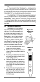
6. Replace the computer cover and plug in your computer. 7. Connect the telephone cable from the modem's LINE connector to the telephone wall jack. See Figure 2-2. 8. Optionally, connect your telephone to the modem's PHONE connector. 9. Optionally, connect your microphone to the modem's MIC jack. 10. Optionally, connect your speakers into the modem's SPK jack. 11. Turn your computer on. Your modem is now installed. 2.
The Install From Disk dialog box now instructs you to “Insert the manufacturer's installation disk into the drive selected, and then click OK.” Insert the modem's Utility diskette into the disk drive and type A:\ (or B:\ if inserted in drive B) in the “Copy manufacturer's files from:” box. Click “OK.” Windows 95 may request its own installation disks for some files. Insert the Windows 95 disks as required. When all necessary files are copied, the modem is configured.
MANAGER|MAIN|CONTROL PANEL, click on PORTS and follow Windows 3.1x user's manual instructions on configuring the installed modem COM port. Proceed to Section 2.5, Software Installation/Configuration. 2.5 Software Installation and Configuration You are now ready to install and configure the communication software. Refer to your software manual for installation procedures. We suggest the following communication parameters when you first use your data communication software.
2.7 Testing Your Modem After Installation In order to test your modem you should be familiar with your communication software. Load and set up your communication software and enter into “terminal mode.” Make sure that the COM Port and IRQ settings of the modem match the software. Type AT on your terminal screen and press ENTER. You may see “AT”, “AATT” or nothing on the screen. In any case, the modem should respond with an OK or 0.
Section Three - AT Command Set 3.1 Executing Commands Commands are accepted by the modem while it is in Command Mode. Your modem is automatically in Command Mode until you dial a number and establish a connection. Commands may be sent to your modem from a PC running communication software or any other terminal devices. Your modem is capable of data communication at rates of: 300, 1200, 2400, 4800, 9600, 14400, 19200, 28800, 38400, 57600, and 115200 bps.
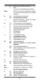
@ ! ; DS=n E_ wait for five seconds of silence flash return to Command Mode after dialing Dial one of the four telephone numbers (n=0-3) stored in the modem’s non-volatile memory.
W1 W2 X_ X0 X1 X2 X3 X4 Y_ Y0 Y1 Z_ 3.4 Z0 Z1 Report line speed, error correction protocol, and DTE speed. Report DCE speed only Hayes Smartmodem 300 compatible responses/blind dialing.
&P2 &P3 Same as &P0 setting but at 20 pulses per minute Same as &P1 setting but at 20 pulses per minute &R_ &R0 &R1 Reserved CTS operates per flow control requirements &S_ &S0 &S1 Force DSR Signal High (ON) DSR off in command mode, on in on-line mode &T_ &T0 &T1 &T3 &T4 Ends test in progress Perform Local Analog Loopback Test Perform Local Digital Loopback Test Grant Remote Digital Loopback Test request by remote modem Deny Remote Digital Loopback Test request Perform a Remote Digital Loopback Tes
300, 33600. Parameter “a” specifies the modulation protocol desired where: 0=V.21, 1=V.22, 2=V.22bis, 3=V.23, 9=V.32, 10=V.32bis, 11=V.34, 64=Bell 103, 69=Bell 212, and 74=VFC. Parameter “b” specifies automode operations where: 0=automode disabled, 1= automode enabled with V.8/V.32 Annex A. Parameter “c” specifies the minimum connection data rate (300-33600). Parameter “d” specifies the maximum connection rate (300-33600).
\N3 \N4 \N5 3.6 Fax Class 1 Commands +FAE=n +FCLASS=n +FRH=n +FRM=n +FRS=n +FTH=n +FTM=n +FTS=n 3.7 V.42/MNP/Normal data link V.
+FPTS= +FREV? +FSPL +FTSI: 3.
Table 4-1 S - Registers Register Function Range/units S0 S1 S2 S3 S4 S5 S6 S7 S8 S9 S10 S11 S12 S13 S14 Default Auto-answer Ring 0-255 /rings 0 Ring counter 0-255 /rings 0 Escape code character 0-127 /ASCII 43 Carriage return character 0-127 /ASCII 13 Line feed character 0-127 /ASCII 10 Backspace character 0-32, 127 /ASCII 8 Dial tone wait time 2-255 /seconds 2 Remote carrier wait time 1-255 /seconds 50 Comma pause time 0-255 /seconds 2 Carrier detect response time 1-255 /0.
S49-81 Reserved S82 Break options 3, 7, or 128 S83-85 Reserved S86 Connection failure code 0, 4, 5, 9, 12, 13, 14 S87-S90Reserved S91 Transmit attenuation 0-15/dBm S92 Fax attenuation 0-15/dBm S95 Extended result code optionsBit-mapped register 128 * 10 10 Section Five - Result Codes OK 0 RING 2 ERROR 4 NO DIALTONE 6 NO ANSWER 8 CONNECT 2400 10 CONNECT 9600 12 CONNECT 12000 14 CONNECT 19200 16 CONNECT 33600 84 CONNECT 57600 18 CONNECT 1200TX/75RX 22 FAX 33 CARRIER 300 40 CARRIER 75/1200 45 CARRIER 2400 47
data to it. Similarly, IRQ settings must be set correctly to receive data from the modem. 2. Make sure that your modem is initialized correctly. Your modem may have been initialized to not display responses. You may factory-reset the modem by issuing AT&F and press ENTER. The factory default allows the modem to display responses after a command has been executed. Modem does not dial. 1. Make sure the modem is connected to a working phone line.
and XON/XOFF software flow control is disabled in the communication software. 3. Make sure the data speed is not faster than your computer's capability. Most IBM compatibles are capable of 19,200 bps under DOS and Windows. Operating at higher speeds under Windows requires a faster CPU (386/486 or better), a high performance replacement Windows 3.1x comm.drv, or Windows 95. Modem experiences bursts of errors or suddenly disconnects while communicating with a remote modem. 1.
Power: Temperature: Caller ID: PnP: Speakerphone: 0.75 W 0 to 55 degrees C (Operating) Yes Revision 1.0a Full-duplex with DSP echo cancellation Appendix B - FCC , DOC & Other Notices FCC Compliance This equipment complies with Part 68 of the FCC Rules. On this equipment is a label that contains, among other information, the FCC registration number and Ringer Equivalence Number (REN) for this equipment. You must, upon request, provide this information to your telephone company.
cause harmful interference to radio or television reception, which can be determined by turning the equipment off and on, the user is encouraged to try to correct the interference by one or more of the following measures: • Reorient or relocate the receiving antenna • Increase the separation between the equipment and the receiver • Connect the equipment into an outlet on a circuit different from that to which the receiver is connected • Consult the dealer or an experienced radio / TV technician for help Not
to a telephone loop which is used by the device, to prevent overloading. The termination on a loop may consist of any combination of devices subject only to the requirement that the sum of the Load Numbers of all the devices does not exceed 100. UL Notice Caution: This internal modem adapter is to be installed in UL Listed computers only, Always disconnect the modem adapter from the telephone system during installation or when the cover is removed from the computer. First Edition GZ/DR - Version 1.
21