Congratulations on your purchase of the new PocketWizard MultiMAX digital radio triggering system. T he PocketWizard MultiMAX is a m icrop roces sor-b ased radio slave s ystem that us es advan ced digital sig naling to inc reas e trigg ering rang e, reliability, an d rejec tion of radio noise from other sources. Since it utilizes Transceiver technology, it is both a transmitter and a receiver all in one. It is the most innovative and advanced wireless solution in the photographic industry.
FCC & IC Compliance Information W AR NIN G : Ch anges or mod ifications to this u nit not expres sly app roved by the p arty resp ons ible for c omp liance c ould void the u ser's authority to operate the eq uipm ent. NO TE : This equipm ent has been tested and found to comp ly with the limits for a Class B digital device, pursuant to Part 15 of the FCC R ules. These limits are des igned to p rovide reason able protec tion agains t harm ful interf erenc e in a resid ential installation.
Table of Contents Icon s U sed in this Man ual . . . . . . . . . . . . . . . . . . . . . . . . . . . . . . . . . . . . . . . . . . . . . . . . 8 Featur es . . . . . . . . . . . . . . . . . . . . Communication Technology Bas ic F eatures . . . . . . . . . . Sp ecial Featu res . . . . . . . . . . . . . . . . . . . . . . . . . . . . . . . . . . . . . . . . . . . . . . . . . . . . . . . . . . . . . ...................... ...................... ...................... ...................... . . . .
Men u S ystem . . . . . . . . . . . . . . . . . . . Navigation . . . . . . . . . . . . . . . . . LCD C ontrast Adjustment Num eric Entry . . . . . . . . . . . . . . . . . . . . . . . . . . . . . . . . . . . . . . . . . . . . . . . . . . . . . . . . . . . . . Main Menu . . . . . . . . . . . A: Advanced Menu B: Basic Settings . C: Counter Menu . D: G o Ad vanced . . D: G o Nor mal . . . . . . . . . . . . . . . . . . . . . . . . . . . . . . . . . . . . . . . . . . . . . . . . . . .......
O ther F eatures . . . . . . . . . . . . . Keypad Lock . . . . . . . . . . Hig h V oltage Protec tion . Relay Mode . . . . . . . . . . . Sof tware V ersion D isplay . . . . . . . . . . . . . . . . . . . . . . . . . . . . . . . . . . . . . . . . . . . . . . . . . . . . . . . . . . . . . . . . . . . . . . . . . . . . . . . . . . . . . . . . . . . . . . . . . . . . ............... ............... ............... ............... ............... . . . . . . . . . . . . . . . . . . . . .
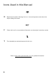
Icons Used in this Manual N N Read the information following this icon. It shows important notes about the subject being discussed. L L Follow this icon for more detailed information on the subject in another section. ë ë Find valuable tips and techniques with this icon. Ref er to h tt p: // ww w .p oc k et wiz ar d. com / for updated information.
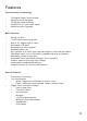
Features Communication Technology • • • • • Fu ll Digital R adio C omm unic ation Microprocessor controlled 32 digitally coded channels Com plex 16 or 2 4 bit c oded s ignal Selective Quad-Triggering Basic Features • • • • • • • • • • • • • Bu ilt-in hot sh oe 1/4-20 female mounting thread B u ilt -in A C ad ap ter jac k (1 .
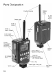
Parts Designation 10
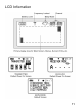
LCD Information 11
Controls Power Switch • T R A N SM IT • RECEIVE • OFF U nit is pow ered on in TR ANS MITT ER (T X) mode U nit is pow ered on in REC EIVER (R X) mode Unit is powered OFF Power Switch Keypad • A B C D L Selec ts Q uad-T riggerin g Z ones and Local. Also used in menu navigation and num eric entry • TEST Triggers MultiMAX. Press to test operation or to trigg er rem ote units and/or attac hed c ameras /flash es • (Back Light) Illuminates LCD and keypad.
Getting Started Battery Information The MultiMAX requires two AA size (IEC: LR6) batteries. T he M ultiMA X will operate norm ally with Nic kel Metal H ydride (N iMH ), Lithium Ion (Li), N ickel Cad ium (N iCad ) and A lkaline batteries. Alkaline batteries are recommended. Ins erting B atteries 1. 2. 3. 4. 5.
The MultiMAX continually regulates the battery power which gives excellent perfor man ce th rough out the life of th e batteries. T he un it will continu e to fun ction normally until the batteries are nearly exhausted. N T he M ultiM AX voltage reg ulation is very ef fic ient. T here is only a s mall bene fit when using Lithium batteries. Lithium batteries are designed for the quick burst high current draw found in cameras and portable flash devices.
Care and M aintenance To ensure continued reliability, please follow these guidelines: • D o n ot s u bjec t u nit s to h ig h m ec h an ic al s h oc k (d o n ot d rop ! ) • Kee p u nit d ry.
Quick Setup - Basic Radio Slave Operation Basic Setup for Remote Flash N Turn off all equipment before installing batteries or making connections! 1. Install 2 AA batteries in each MultiMAX 2. Connect camera to first MultiMAX: a. Slide u nit into cam era hot s hoe - orb. Us e sync cab le (inclu ded) to c onnec t cam era’s P C ter min al to C A M ER A / P O R T 1 3. Connect flash to second MultiMAX a. Use flash cable to connect flash unit’s sync terminal to FLASH / PORT 2 4.
Trig gering M ultiple Flashe s W ith M ultiple RE CE IVE U nits Multiple remote flash units m ay be triggered in sync w ith each other. 1. 2. 3. 4. Ins tall batter ies in each add itional M ultiM AX un it Us e flash cab le to conn ect eac h add itional flash u nit’s s ync term inal to F LA S H / P O R T 2 Set power switch on each additional MultiMAX unit to RECE IVE mode Set all Mu ltiMA X un its to s am e ch ann el as T R AN SM IT un it You ’re all s et! U se the camera n orm ally.
Standard Radio Operation Transceiver Control T he M ultiMA X operates as either a tran sm itter or a receiver. T o us e the M ultiMA X as a Transmitter (sending device) set the power switch to TRAN SMIT. To use the MultiMAX as a Receiver set the power switch to RECEIVE. L T here is a s pec ial mode th at enables a Mu ltiMA X to autom atically switc h fr om RE CE IVE to TR AN SM IT then b ack to R EC EIV E w hile triggering a remote c amera. Read the Relay M ode section, Page 40, for more information.
Co mp atibility MultiMAX channels are compatible with all PocketW izard radio slave products per the table below: Digital Radio Mo del M ultiM AX Co m pa tible Ch an ne ls Poc ketW izard 10 C han nel C lass ic 1-10 Poc ketW izard 16 C han nel C lass ic 1-16 PocketW izard Plus 1-4 PocketWizard MAX 1-16 17-32 Quad-Triggering or Fast Mode Sekon ic D igital Rad io Tran sm itter Module RT-32 (L358, L608, L608 CINE) 1-16 17-32 Quad-Triggering Sekonic Digital Radio Receiver RR-4 1-4 Sekonic Digital R
Selective Quad-Triggering (A B C D keys) This powerful feature is used to individually control up to 4 sets of M ultiMA X un its (s et for R EC EIV E m ode) on the s ame c hann el. Eac h keypad letter, A B C D refers to an individual zone. Each zone can be independently selected or deselected from a MultiMAX (set for TR AN SM IT m ode). Follow the steps below to test Quad-Triggering: 1. Set one MultiMAX to TR ANS MIT mode 2.
C lass ic C han nels C lass ic c han nels are c om patib le with early Poc ketW izard m odels an d the P ocketW izard P lus. Selec tive Q uad -T rigg ering is on ly available in channels 17 through 32. In channels 1 through 16 the display will show CLASSIC CHANNEL and zones A B C D do not app ear. T he A key simply toggles the remote receivers on or off and is displayed on the main screen as R.
True Confirmation Bec aus e the M ultiMA X is a tru e trans ceiver it autom atically conf irms triggerin g. It can perform this on two levels: it confirms the round trip radio signal and can c onfirm actual flash sync with an optional flash confirmation cable. It does this for all QuadT rigg ering zones on every tr igge r. C onf irm ation is indic ated vis ually on th e m ain screen and audibly using beep modes. L For aud ible conf irmation s ettings see the Beep Menu section, Page 29.
N Confirmation can only be performed using MultiMAX units on channels 17 and higher. PocketW izard Plus, Classic, and the original MAX do not perform confirmation. N True Confirmation is designed to work with one MultiMAX (set for RECEIVE mod e) per zon e. Mu ltiple RE CE IVE units set to the s ame c hann el and zon e will not individually confirm and may cause incorrect confirmation errors.
Menu System Navigation Man y functions of the M ultiMA X are acc ess ed throu gh eas y-to-navigate m enus . Press ~ /M E N U to enter the menu system. Menu items are selected by using the A B C D L keys.
Num eric Entry Several menu items require a number or value to be entered. Numeric entry is performed with A B C D and keys. T he A B C D keys each select and add 1 to a specific digit as follows: A– B– C– D– selec ts an d add s 1 selec ts an d add s 1 selec ts an d add s 1 selec ts an d add s 1 to the 4 th digit from the righ t to the 3 rd digit from the righ t to the 2 nd digit from the righ t to the rightm ost d igit O nc e a digit has been s elected, u se th e keys to adjust the number.
Main Menu From the main screen press ~ /M E N U to enter the Main Men u. P ress a letter to either proceed to another menu or perform a function per the list below. A: Advanced M enu – ~ /M E N U A Press A to enter the A dvanc ed M enu. T he A dvanc ed Menu con tains D elay mod es ( inc ludin g R ear C urtain Sync), Intervalometer, Multipop, and SpeedCycler modes. Main Menu G o Ad vanced B: Basic Settings – ~ /M E N U B Press B to enter the Basic Settings menu. It contains Contact time and Beep menu.
Basic Settings Press ~ /M E N U B to enter the Basic Settings menu. Press the corresponding letter for the setting you wish to adjus t. A : C o nt ac t T im e – ~ /MENU B A Basic Settings Menu Con tact tim e is the leng th of tim e that C AM ER A / P O RT 1 or F LA SH /PO RT 2 outp uts remain contacted. The default Contact Time of 0.12 is enough to trigger most cam era motor drives and flashes. Many photographers will never need to adjust this num ber.
For trigg ering rem ote cam eras , a long er c ontac t tim e allows for c ontin uou s r epeatab le motor d rive triggering (examp le: 5 fram e burs ts every trigger ). It also allows for con trolled bulb exposu re.
B: Beep Menu – ~ /MENU B B T his m enu c ontrols th e beep f unc tions of a Mu ltiMA X. Pres s th e corres pond ing letter to set th e desired func tion of the built-in speaker. A: Beep on All – ~ /MENU B B A Mu ltiMA X will beep on all triggering, c onfirm ation errors , and zer o coun ts as indic ated below as well as on any key pressed.
Counter Menu Press ~ /M E N U C enter the Counter Menu. This menu controls the counter functions of the MultiMAX. The cou nter c an s how th e total num ber of trig gers . It can also c oun t up or dow n f rom a set valu e. C oun t is incr emen ted on every trigger from any sou rce: PO RT 1, TEST button , Hot S hoe, or R adio T rigger. Counter Menu A: C ount U p + R eset – ~ /M E N U C A Count is set to COU NT UP (example: 0,1,2,3,...) and the c ounter is reset to 0.
C: C lear / Res et – ~ /M E N U C C Cou nt direc tion is not c hang ed. C ounter is reset to 0 if cou nt direc tion is s et to up, or the c oun ter is res et to the load value if c oun t direc tion is set to dow n. If the c oun ter is disab led, then th is fu nc tion will enable the c ounter u sing the last c ount d irection s et. The Counter is cleared and reset in this fashion when the unit is powered down. ë Us e ~ C C as an eas y to remem ber qu ick key c omb ination for f ast c ounter res et.
Advanced Menu Press ~ /M E N U A to enter the A dvanced Me nu . T his menu contains the advanced functions of the MultiMAX. Precision timing and sequencing operations are available in this menu. L Press ~ /M E N U D to cancel advanced functions and return to normal mode. See the section on D:Go Adv anced and D:Go Norm al, Pag e 26.. R EC EIVE un it Advanced Menu A: Delay Menu - TRANSMITTER – ~ /M E N U A A En ters th e delay menu for M ultiMA X un its (s et for T RA NS MIT mod e).
B: R em otes O nly – ~ /M E N U A A B En ters the n um eric entry s cr een. D elays th e R adio rem ote un its on ly. PO R T 2 w ill trigger immediately. Remote units will trigger after the displayed delay. If the contact time for the M ultiM AX (s et for T R AN SM IT mo de) is longer than th e delay, P O R T 2 w ill remain con tacted f or the delay time rath er than th e contac t time. C : R ear C urtain – ~ /M E N U A A C En ters th e Rear C urtain s creen .
A: Delay Menu - RECEIVER – ~ /M E N U A A En ters th e delay menu for a M ultiMA X (s et for RE CE IVE mod e). Eac h R EC EIV E u nit can have its own d elay for seq uenc es or f or sync hronization . T o easily delay all RECEIVE units the same amount, use the T ran sm itter’s d elay. N RE CE IVE un its set to delay do not perform confirmation. R EC EIVE un it Delay Menu A : P O R T 1 + PO R T 2 – ~ /M E N U A A A Enters the numeric entry screen.
C: E qualize – ~ /M E N U A A C Equalize Mode is a specialized delay mode for synchronizing multiple cameras to one f las h . T h is m od e is d es ig ned to w or k w it h s h ut ter sp eed s up to 1 /1 25 on s om e cameras, but there are many factors that could affect operation. L Read the Camera Equalization section, Page 43 , before continuing. Equalize mode is designed to be used with at least 3 MultiMAX units (set in RECEIVE mode).
B : In te rv a lo m e te r ( T im e L ap s e P ho to g ra p hy ) – ~ /M E N U A B En ters th e Intervalometer interval s etting s creen . Intervalometer can be used to trigger a flash or a cam era at a set interval (time g ap betw een trigg ers) f or a set nu mber of trigg ers . T he interval tim e is s et in one second increments up to 64000 seconds for a maxim um of 99 99 trig gers . 1. 2. 3. 4. 5. 6.
ë For delays longer than the 6.4 seconds (maximum available in delay modes) use Intervalometer or Multipop mode. Set the interval to the desired delay. Set the count to 1. A ttac h your cam era to P O R T 1 an d trig ger th e M ultiM AX . T he c am era will trigg er aft er the set in terval. N Contact time affects Intervalometer mode. If the contact time is less than one second then Intervalometer will function normally.
The following chart is a starting point for calculating how the number of flashes or pops affec ts F -stop s. S ince every flas h un it is diff erent, us e a light m eter or other m ethod for more precise calculations. Number of Pops Stops Number of Pops Stops 1 Add 0 stops 6 Add 2.5 stops 2 Ad d 1 s top 8 Add 3 stops 3 Add 1.5 stops 12 Add 3.5 stops 4 Add 2 stops 16 Add 4 stops N Con tact tim e is aff ected b y Mu ltipop m ode.
D: Fast Mode - RECEIVER – ~ /M E N U A D The MultiMAX is designed to sync cameras and flash units at shu tters s peeds up to 1 /250 th for m ost f ocal plane s hutters (35m m) and 1 /500 th for m ost leaf shutters. Some c amera and flash combinations are capable of fast sync speeds up to 1/1000th. The Mu ltiMA X (s et for R EC EIV E m ode) is c apable of operation at these speeds in Fast M ode. Check your camera’s and flash unit’s manuals for the maximum sync sp eeds allowed by your eq uipm ent.
R e la y M o d e ( R E C EI VE M o d e O nl y) – L In th is m ode a remote cam era’s mo tor dr ive is triggered by a MultiMAX (set for RECE IVE mode). The MultiMAX then switches to TRAN SMIT m ode and waits for a sync pulse from the camera. Upon getting the sync pulse from the cam era the unit then triggers remote flash units via radio and returns to RECEIVE mode, ready to trigge r the c am era aga in. U sin g th is mode it is possible, using only 3 PocketW izard units, to have complete wireless triggering.
Applications of Advanced Functions The applications below are unique ways to use the advanced functions of the MultiMAX. Many of them require fine-tuning or adjustment to work with different cam era equip men t. Alw ays perf orm tes t exposu res to ins ure reliable res ults. Self-Timer or Cable Release Delays, or Intervalometer and Multipop with a count of 1, can be used as a cam era timer for self portraits or as a trigger delay to reduce camera shake.
Us e the form ula below to help calc ulate your m aximum saf e sh utter s peed b ased on your flash durations. L Ref er to the Tim e Co nv ersion C harts sec tion, Pag e 55, to c onvert frac tions in to dec imals for the f ormu la. 1. 2. 3. 4. Add your maximum (longest) flash durations together (decimals, not fractions) Ad d anoth er 0.00 2 (f ocal plane) or 0.
Camera Equalization Eq ualization, or syn ch ronizing mu ltiple cam eras to th e sam e flash , requires prec ision timing . Even th ough we perc eive camer a triggering activity as ins tantaneous , it is not. Even th e flash , whic h app ears to p rovide light only for an instan t, has a tim e duration (flash duration) that needs to be factored into synchronization calculations. Every c amera h as a delay from the time it is triggered until the s hutter is fully open.
• M u lt ip le m ec h an ic al s ys tem s – c am eras that h ave ma ny c han geab le mech anic ally interac ting parts (film bac ks , motor drives, lens sh utter s) are likely to have diff erent lag tim es w ith diff erent hard ware c omb inations. A leaf sh utter is in th e lens s o ch anging lenses on a leaf s hutter c amera w ill chang e lag time. In s ome m edium form at cam eras h aving the f ilm bac k loaded vers us unloaded c an m ak e a s ig nif ic an t d if fer en c e.
ë Speed is not the most important factor in camera equalization, consistency is. If a slow c amera h as extrem ely cons istent lag tim es it will be a better eq ualization can didate than a faster but inc ons istent c amera. T he reas on wh y it is imp ortant to know the ap proxim ate fas test lag tim e for a c am era, es pec ially an inc ons isten t one, is to calculate margin of error (discus sed later in this section).
N If your c amera’s maxim um sync sp eed is s lower than the nu mb er listed th en you mu st u se th e slower s ync s peed. C amera eq ualization does not give a cam era fas ter sync sp eeds than th e cam era is des igned to h andle. For all shutters it can be assumed that a camera with faster external flash sync speeds (X s ync) will have faster sh utter travel than c ameras with s lower X s ync s peeds . Fas ter sh utter travel times incr ease the allowab le variance.
O ne U nit Eq ualization To equalize two cameras and one flash at 1/125 with one MultiMAX, follow these steps: 1. 2. 3. 4. 5. 6. 7. 8. 9. Set the MultiMAX to REC EIVE mode Measure lag times of cameras as described and record the fastest lag for each D eterm ine w hic h c am era is fas ter and w hic h is slow er overall D e ter m in e th e d elay tim e a. If the s low cam era is m ore con sis tent us e this f ormu la: i.
If using both Mu ltiMA X units as R EC EIVE units being triggered by any PocketW izard Transmitter follow these steps: 1. 2. 3. 4. 5. 6. 7. 8. 9. 10. L Set both units to REC EIVE mode Measure lag times of cameras as previously described and record the fastest lag for each D eterm ine w hic h c am era is fas ter and w hic h is slow er overall D e ter m in e th e d elay tim e a. If the s low cam era is m ore con sis tent us e this f ormu la: i.
Eq ualization A djus tmen ts W ith all the variable factors above it may seem that perf ormin g the m ath nec ess ary for equalization is daunting. Here are some techniques for fine- tuning or adjusting equalization times without using specific math: On some 35m m c ameras you can gauge timing without using film. If your camera allow s trigger ing with the film bac k op en you can ver ify s ync hroniz ation visu ally. 1. 2. 3. 4. 5.
Technical Information Specifications W eight: Dimensions: 5.4 ou nc es w ith alkaline batteries 1.4 inc hes deep x 2.1 inc hes wid e x 4.0 inc hes tall (b ody on ly) Flexible antenn a = 2.4 inch es tall. 0.3 in ch es in d iameter Batteries : 2 x AA (IEC :LR 6), 1.5 V b atteries, alkaline rec omm ended Read the Getting Started sec tion, Pag e 13, f or mor e inform ation AC Adapter Jack: 3 V DC unreg ulated, 0.3 A (3 00 m illiamp) or h igher 4.5 V DC regulated, 0 .
HOT S HOE NOT E #2: Some cameras may exhibit undesirable behavior if the RE CE IVE unit is mou nted in th e cam era hot s hoe wh en that c amera is being f ired r em ot ely. S om e c am er as ’ h ot s h oe an d m ot or dr ive c on tac ts m ay s h ar e s om e connections. This can cause the camera to lock up or stop operating normally. If your camera does not function properly in this mode then remove the unit from the cam era’s hot s hoe. Radio Information • • • T rans mit O utpu t Pow er: 0.
M aximum and M inimum Settings The following table details the maximum and minimum values allowed for each numeric entry setting available in the MultiMAX. Setting M axim um M inimum C o nt ac t T im e 640 .00 s econ ds or 10 minutes, 40 seconds .01 seconds D e lay T im e 6.4000 seconds .0001 seconds (add 0 .
Troubleshooting W hen in dou bt ! Many issues can be resolved by powering the unit off and then back on again or by resetting to factory default settings. Before proceeding to any other troubleshooting procedure follow these steps: 1. 2. 3. Set power to OFF W ait 10 second s or until display completely blanks Set p ower to R EC EIV E or T RA NS MIT Reset to Default Factory Settings 1. 2. 3. 4.
Radio Performance The MultiMAX is an advanced digital radio system. Its true digital technology guarantees optimum interference rejection while maintaining high performance. As with all radio devices (c ell phones, walkie talkies, cordless s ound systems ) there are som e situations wher e perform anc e may be d egraded by outs ide fac tors. F or maximum radio performance for the MultiMAX, or any radio device, follow the guidelines below: • • • • • • Kee p an tenn as p arallel.
Time Conversion Charts Frac tions to D ecim al: Here are some comm on photographic fractions in decimal values. All numbers are rounded to the nearest .0001 or 1/10,000th. L T hes e times are not R ear C urtain S ync tim es. T hes e are prec ision n um bers . Rear Curtain Sync numbers are always less than the exact conversions. Refer to the Re ar C urt ain section, Page 33, for more information. Fraction Decimal Fraction Decimal ½ 0.5 seconds 1/180 0.0056 seconds 1/4 0.25 seconds 1/200 0.
Manual Revision 1.