High Performance Ethernet PCMCIA Adapters PCN2000 Series User's Guide Part #MAN004 Rev. 1.
REPAIR INFORMATION FORM Please take a moment to note the following information. Include this form in the unlikely event that you need to return the product for warranty service. Refer to Section Eight for complete Warranty information and procedures on returning your product.
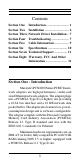
Contents Section One Section Two Section Three Section Four Section Five Section Six Section Seven Section Eight Introduction ............................ 1 Installation .............................. 2 Network Driver Installation .. 7 Troubleshooting ...................... 7 Cable Information .................. 9 Specifications ........................ 10 Technical Support ................ 11 Warranty, FCC And Other Information ...........................
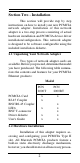
Section Two - Installation This section will provide step by step instructions on how to install your new PCMCIA network adapter. Installation of this network adapter is a two-step process consisting of actual hardware installation and PCMCIA device driver installation/configuration. This network adapter is designed to be software configurable using the included installation diskette. 2.1 Unpacking Your Network Adapter Two types of network adapter cards are available.
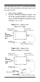
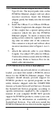
tions described in your PC's manual regarding static electricity discharge at all times when working with your PC. 1. 2. Turn off the computer Hold the PCMCIA Ethernet adapter with the 68-pin female PCMCIA connector facing an available PCMCIA Type II slot (refer to Figure 1-A or 1-B). Figure 1-A Adapter with 10Base-T Coupler 68-pin female PCMCIA connector Female Media Coupler connector To PCMCIA Type 2.
3. 4. 5. Insert the Ethernet adapter into the PCMCIA Type II slot. The keyed guide slots on the PCMCIA Ethernet adapter will not allow incorrect insertion. Insert the Ethernet adapter gently but firmly into the slot until it stops. Insert the 10Base-T (or 10Base-2/10BaseT) Media Coupler into the adapter. One end of this coupler has a special spring-action connector which fits into the PCMCIA Ethernet adapter.
driver diskette. Consult the README file on the driver diskette for specific instructions on how to install the driver. Note: If you are unable to obtain Socket Service and Card Service from your computer manufacturer, you may still be able to use the PCMCIA Ethernet adapter with the included PCMCIA device driver. Consult the README file to determine if your computer is supported in this configuration and for instructions on how to proceed.
CONFIG.SYS, add the above example to your CONFIG.SYS by using a text editor. Consult your memory manager's manual for the appropriate exclusion parameter if you are not using the Microsoft memory manager. The PCMCIA device driver allows selection of operating parameters such as I/O Base Address and IRQ selection. The recommended adapter configuration parameters are: I/O Address: 0300H IRQ Line: 5 2.4 Testing The Adapter It is not necessary to test the PCMCIA Ethernet adapter.
7. 8. mit/receive tests on the network link Interrupt Test: Checks Interrupt Line Network Function: Performs network packet transmit/receive tests Section Three - Network Driver Installation The supplied network drivers allow the Ethernet adapter to work with various network operating systems (i.e., Novell Netware, Microsoft LAN Manager, etc.). Drivers for most popular network operating systems are included in the driver diskette in separate subdirectories. Each directory also includes a README.
after reading the following information, contact your dealer or vendor for assistance. Most adapter failure after installation is caused by: A) Incorrectly installed PCMCIA driver, B)Not excluding memory address D400-D7FF when using a memory manager, C)I/O base address and IRQ Line conflict, or D)Cable problems. 4.1 Incorrectly Installed PCMCIA Driver The included PCMCIA driver runs as a Card Service Client and should only be loaded after the Socket and Card Services are loaded. Be certain that the CONFIG.
system may already use addresses 0300H or 0320H (example: sound/audio card). Vary the settings on your network adapter by running the PCMCIA device driver with different I/O port addresses and IRQs to eliminate the conflict. Running the diagnostic program will also help to detect configuration conflicts. 4.4 Cable Problems A) Observe the green Link Status LED if you are using a 10Base-T network. Turn on the computer. Connect the network cable and observe the green LINK LED.
PCN2000BT Supports both 10Base-2 and 10Base-T networks. 10Base-T networks use unshielded twisted-pair cable and 8-pin RJ-45 modular connectors. Use only 22-26 AWG 2-pair 100 ohm/ft. UTP with two to three twists per foot. The cable must use solid copper conductors and UL codes CM, CMR, and CMP are required. The computer on the network is connected via a star topology (i.e. each node is connected to a HUB, not to each other). Maximum cable length is 300' (100 m).
Section Seven - Technical Support In the unlikely event you experience difficulty in the use of the product, or if it does not operate as described, we suggest you: (1) consult the Troubleshooting section of this guide and (2) consult with your dealer. If you have not referred to the Troubleshooting section, there is a good chance the solution to your problem is there. If you still can not solve the problem, call the Service Center at (201) 579-2954 between 9:00 a.m. and 5:30 p.m.
(also enclose a check for out-of-warranty repair). Enclose your check or Postal Money Order for $7.50 to cover the cost of return shipping/handling. Please do not send cash or stamps. RMA received without the $7.50 fee will not be processed. 4. After wrapping the package securely for shipping, print your name, return address and the RMA # clearly on the outside of your package. 5. Ship the unit prepaid via UPS or the U.S. Postal Service to the address supplied by the technician when you call.