High Performance Software Configurable 16-bit ISA NE-2000 compatible Ethernet Adapters NX-16 Series User's Guide Part #MAN005 Rev. 1.
REPAIR INFORMATION FORM Please take a moment to note the following information. Include this form in the unlikly event that you need to return the product for warranty service. Refer to Section Eight for complete Warranty information and procedures on returning your product.
Contents Section One Section Two Section Three Section Four Section Five Section Six Section Seven Section Eight - Introduction ......................... 1 Installation ........................... 2 Driver Installation .............. 7 Troubleshooting .................. 7 Cable Information .............. 9 Specifications ..................... 10 Technical Support ............. 11 Warranty, FCC And Other Information ........................
Minimum hardware requirements are an IBM PC/XT (or better) fully compatible PC with 512K RAM running DOS 3.3 or higher. The network operating system you use may have higher requirements. Section Two - Installation This section will provide step by step instructions on how to install your new Maxtech network adapter. Installation of this network adapter is a two-step process consisting of actual hardware installation and card configuration.
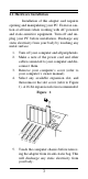
2.2 Hardware Installation Installation of this adapter card requires opening and manipulating your PC. Exercise caution at all times when working with AC powered and static-sensitive equipment. Turn off and unplug your PC before installation. Discharge any static electricity from your body by touching any metal surface. 1. 2. 3. 4. Turn off your computer and all peripherals. Make a note of the power cord and other cables connected to your computer and disconnect them.
. 7. 8. 9. Carefully install the adapter by firmly pressing the card into the slot you have chosen, applying even pressure until the adapter is completely seated in the slot. Fasten the retaining bracket with the screw from the slot cover. Make sure the adapter is properly aligned. Store the slot cover for future use. Replace the computer cover and reconnect the power cord and all cables. Attach the network cable to your adapter. 2.
Running the SETUP program 1. Insert the installation diskette into your drive, log on to that drive, and run the SETUP program in the \DIAG subdirectory. Assuming that your have inserted the diskette in drive A, you would type the following at the DOS C: drive prompt: A: [ENTER] \DIAG\SETUP [ENTER] 2. 3. Select the network adapter that you would like to configure (if you have more than one adapter installed). Otherwise press the Enter key if you have only one adapter installed.
2.4 Testing The Adapter The SETUP program provides an option in its main menu for adapter diagnostics. One or more PCs on the network can run the test simultaneously. The Test Adapter option runs several tests and the results are indicated by either PASS or FAIL. Make sure that the network cable is attached (and properly terminated if using a BNC connection) to the adapter when using this option. If any test fails, the program notifies you of the error and suggests actions to correct the problem.
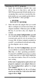
sure that the notch on the ROM matches that on the socket (refer to Figure 2). Figure 2 Align ROM and socket notches 2. 3. Configure the adapter using the SETUP program to enable the Boot ROM function by selecting the appropriate address from the Boot ROM Base Address option. Refer to Section 2.3 for more information on running the SETUP program. Follow the Remote Boot Workstation installation procedure given in your network operating system manual (i.e.
README.TXT file describing the driver. Refer to the RELEASE.TXT file on the installation diskette for more information on the available drivers. Section Four - Troubleshooting This section describes some of the common problems you may encounter while using your network adapter. When troubleshooting, you should make sure that the network you are connected to is functioning. If you suspect that the adapter is malfunctioning, replace it with another adapter which is known to function properly.
4.2 Cable Problems A) Observe the green Link Status LED if you are using a 10Base-T network. Turn on the computer. Connect the network cable and observe the green LINK LED. If the LED is ON, then the system is connected. Otherwise check for a proper RJ-45 connection. B) Make sure the coaxial cable is properly terminated if you are using a 10Base-2 network. Each end of a coaxial segment must be properly terminated with a 50-ohm terminator.
must use solid copper conductors and UL codes CM, CMR, and CMP are required. The computer on the network is connected via a star topology (i.e. each node is connected to a HUB, not to each other). Maximum cable length is 300' (100 m). 10Base-2 networks uses a single conductor coaxial cable and BNC connectors. Use only RG-58A/U or RG-58C/U coaxial cables. Each network node is connected to the coaxial cable via a T-connector (included). The minimum distance between T-connectors is 1.6' (0.5m).
Section Seven - Technical Support In the unlikely event you experience difficulty in the use of the product, or if it does not operate as described, we suggest you: (1) consult the Troubleshooting section of this guide and (2) consult with your dealer. If you have not referred to the Troubleshooting section, there is a good chance the solution to your problem is there. If you still can not solve the problem, call the Maxtech Service Center at (201) 579-2954 between 9:00 a.m. and 5:30 p.m.
4. 5. (also enclose a check for out-of-warranty repair). Enclose your check or Postal Money Order for $7.50 to cover the cost of return shipping/handling. Please do not send cash or stamps. After wrapping the package securely for shipping, print your name, return address and the RMA # clearly on the outside of your package. Ship the unit prepaid via UPS or the U.S. Postal Service To the address provided by the technician when you call. We recommend that the unit be insured.