
Specifications


2
MaxStream XStream-PKG Wireless Modem Operation Manual
2.0 Installation
This section describes procedures for connecting the MaxStream XStream-PKG wireless modem to a host device.
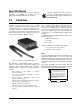
Immediately after unpacking, visually inspect the modem to ensure that all components are included and
undamaged. The shipping carton contains the modem, power supply, cabling, and this manual.
The MaxStream XStream-PKG wireless modem connects to a host device using a 9 pin RS-232 D-Sub connector.
This connection supplies serial communications hookup. The power supply plugs into a round pin 7-18VDC plug.
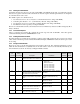
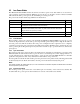
The following illustration shows the package endplate.
Figure 2-1. MaxStream XStream-PKG Endplate
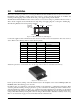
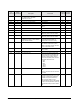
Connect the supplied serial communications cable into the 9 D-Sub connector and attach the other end to the host
device. Refer to the following chart for serial connector pinouts.
Attach the optional 3" or 6" antenna to the opposite side of the modem (see antenna location below).
Figure 2-2. Antenna Location
Power up the modem by turning on the ON switch located on the backplate of the modem. LED lights (RX and
PWR/TX) will be lit indicating power to the unit.
In addition, there is a push button on the antenna endplate of the unit. This is a configuration push button. Hold
down the push button while powering up the unit to go into command mode. Placing the unit in command mode
with the push button is similar to using the “+++” command, except the push button forces the unit to use the default
baud rate instead of the current one. The default baud rate for the unit is 9600 and is the only parameter that can be
changed. Data Bits and Parity and Stop Bits cannot be changed. Their default is: Data Bits = 8, Parity = None, Stop
Bits = 1. See Section 4.0 on page 4 for more information about command modes.
Pin
Signal Type Description
1NC— No connect
2 RXD Output Data
3 TXD Input Data
4 DTR Input Sleep control
5 SGND Ground Common return
6NC— No connect
7RTS Input Binary program control
8 CTS Output Clear to send control
9NC— No connect
Table 2-1. Serial Connector Pinout Assignments
7-18 VDC
RS-232
RX
PWR/TX
ON
1
POWER
SWITCH
UP =