
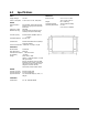
Specifications

8
MaxStream XStream-PKG Wireless Modem Operation Manual
5.0 Networking with the XStream
The MaxStream XStream-PKG wireless modem is built around a peer-to-peer protocol that inherently supports a
multi-drop type network (similar to RS-485). In their default state, any XStream modem will communicate with any
other XStream modem in its default state. When one modem transmits, all other modems within range will tune into
the transmission and output the data received out of the serial port.
While this provides flexibility in system design, addressing the need for isolation and security in a wireless world,
the XStream modules append three levels of addressing to a data packet before transmitting it over the air. Other
XStream radios within range monitor the radio channels and use the addresses to determine what to do with a
packet. There are three types of addressing. They are:
•Vendor IDentification number
•Group addresses
•Radio addresses
5.1 Vendor IDentification Number (VID)
For network security, a system integrator can request a
Vendor IDentification number (VID) that is
programmed into the XStream module at the factory.
This number is stored in permanent memory and can
only be changed at the factory. Only modems with
matching VID numbers can communicate together. The
VID addressing ensures that modems used by one
system integrator are immune to either transmissions or
receptions with other XStream modems which are
located in the same area but not running by the same
system integrator.
5.2 Radio Groups
Within each VID, there are seven available
radio/modem group addresses. Each group utilizes a
different random hopping sequence to navigate through
shared hopping channels. In the event that two modems
from different groups collide on a channel, because
they hop in a different sequence, the two modems will
jump to separate channels after another hop. Using
modem groups, multiple modem pairs can operate in
the same vicinity with minimal interference from each
other. The group parameter is user settable using the
ATHP command or equivalent binary command.
5.3 Radio ADdress (RAD)
Each radio/modem in a sub-domain can be configured
with a 16-bit radio address (RAD) to establish
point-to-point or selective communication between
radio groups. This is done using the ATDT command or
its equivalent binary command. This commands sets a
RAD for a radio. There are 65535 packet addresses
available and has a default RAD of zero. The default
global RAD is 0xFFFF. Every radio in a group receives
packets from a radio with a RAD of 0xFFFF regardless
of what their RAD is set to. Except for global RADS,
only radios with the same RAD can communicate.
If a radio group consists of three or more radios, a RAD
can be used to communicate selectively to individual
radios (radios A, B, and C) as follows:
• Set the RAD of radios A and B to unique values
within the subdomain.
•To communicate only with radio B, set the RAD of
radio C to match that of radio B. Now radios B and C
can transmit and receive data and though radio A will
tune into a transmission, no data will be sent out the
UART of radio A because its RAD doesn’t match.
•When a radio observes that data is being sent to a
RAD that doesn’t match his, it will still listen to the
whole message in order to maintain network
sychronization and will not transmit while a message
is being sent with a different RAD.
5.3.1 RAD Mask
A Radio ADdress Mask is also available to facilitate
networking within a radio group and broadcasting
messages to groups of radios. The RAD Mask is set
using the ATMK command. The RAD Mask is the
same length as the RAD (16 bits) and is set to 0xFFFF
from the factory. Any bits set in the RAD Mask are
compared against the RAD. Any bit cleared in the RAD
Mask are ignored. The RAD Mask is used as the global
address so if the RAD Mask is changed, the global
address will be the new RAD Mask. This allows for
sub-networks of radios which are still independently
addressable and have individual global addresses, i.e.:
0x000F, 0x00F0, 0x0F00, and 0xF000.