DTSU666-HW Smart Power Sensor Quick Guide Issue: 07 Date: 2022-04-27 ZTY0.464.
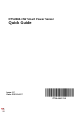
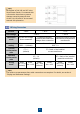
1 Overview 1.1 Dimensions DTSU666-HW 45 mm 35 mm 80 mm 62 mm 101 mm 72 mm Installation position The dimensional tolerance is ± 1 mm. 1.
1.
2 Installing the DTSU666-HW 1. Install the Smart Power Sensor on the standard guide rail of DIN35mm. 2. Press the Smart Power Sensor downwards onto the guide rail, and then push it in place along the guide rail. 1.4 3 3.
Each phase of UA, UB, and UC in the Smart Power Sensor is connected with a fuse and a thermistor to prevent damage caused by external short circuits. UA, UB, and UC do not need external fuse protection. 3.
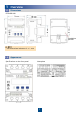
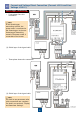
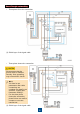
3.3 Current and Voltage Direct Connection (Current ≤ 80 A and Line Voltage ≤ 500 V) SmartLogger networking • Three-phase four-wire connection In the SmartLogger networking scenario, the power meter is connected to the SmartLogger. In the nonSmartLogger networking scenario, the power meter is connected to the inverter. (1) Shield layer of the signal cable • Three-phase three-wire connection (1) Shield layer of the signal cable You need to set parameters after cable connections are complete.
Smart Dongle networking • Three-phase four-wire connection (1) Shield layer of the signal cable • Three-phase three-wire connection (1) Shield layer of the signal cable You need to set parameters after cable connections are complete. For details, see section 4 "Display and Parameter Settings".
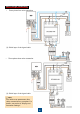
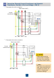
3.4 Connection Through Current Transformer and Voltage Direct Connection (Current > 80 A, Line Voltage ≤ 500 V) Current transformers specifications: The accuracy class is 0.5, and the current on the secondary side is 1 A or 5 A. SmartLogger networking • Three-phase four-wire connection In the SmartLogger networking scenario, the power meter is connected to the SmartLogger. In the nonSmartLogger networking scenario, the power meter is connected to the inverter.
Smart Dongle networking • Three-phase four-wire connection (1) Shield layer of the signal cable • Three-phase three-wire connection Please ensure that the ground cable is installed securely. Poor grounding may cause electric shocks. • • You need to set parameters after cable connections are complete. For details, see section 4 "Display and Parameter Settings". For the three-phase three-wire connection, phase B does not need to connect to a current transformer.
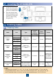
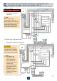
3.4 3.5 • Connection Through Current Transformer and Potential Transformer (Current ≥ 0 A, Line Voltage > 500 V) Three-phase four-wire connection Cable outlet (OUT) Current transformers UA • Cable inlet (IN) UB UC UN Three-phase three-wire connection Cable outlet (OUT) Current transformers Please ensure that the ground cable is installed securely. Poor grounding may cause electric shocks. You need to set parameters after cable connections are complete.
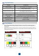
4 Display and Parameter Settings 4.1 Display The button → is used to switch the displays. Set parameter disp to enable the rotation display function. No. Display Description No. 1 Positive active energy = 10000.00 kWh 2 Negative active energy = 2345.67 kWh 3 None parity, 8 data bits, and 1 stop bit; baud rate = 9600 bps (default) 4 011 represents address (default) 5 Phase A voltage = 220.0 V 6 Phase B voltage = 220.1 V 7 Phase C voltage = 220.2 V 8 Phase A current = 5.
4.2 Parameter Settings No. Parameter Value Range Description 1 1–6553 Current transformer ratio 2 0.1–999.9 3 1: 645 2: n.2 3: n.1 4: E.1 5: 0.1 Communication protocol switchover: 1: Factory mode 2: None parity, 2 stop bits, n.2 3: None parity, 1 stop bit, n.1 4: Even parity, 1 stop bit, E.1 5: Odd parity, 1 stop bit, 0.
4.3 Parameter Setting Operations Button description: SET means "confirm" or "cursor move" (when inputting numbers or parameters), ESC means "exit", and → means "add". The default user password is 701.
• Modify user password: 5 Troubleshooting Symptom No display after power-on Cause Analysis 1. 2. The cable connection is incorrect. The voltage supplied to the meter is abnormal. 1. The RS485 communication cable is disconnected, short-circuited, or reversely connected. The communication address, baud rate, data bit, and parity bit of the meter do not match those of the inverter. Troubleshooting Method 1. 2. 1. Abnormal RS485 communication 2. 1. Inaccurate metering 6 2.
Customer Service Contact 7 Customer Service Contact Region Country Email Tel France Germany Spain Europe Italy eu_inverter_support@huawei.com 0080033888888 UK Netherlands Other countries For details, see solar.huawei.com. Australia eu_inverter_support@huawei.com 1800046639 Turkey eu_inverter_support@huawei.com 0080021686868 /1800220036 Malaysia Asia Pacific apsupport@huawei.com Thailand (+66) 26542662 (local call rates) 1800290055 (free in Thailand) China solarservice@huawei.