
Instruction Manual


G9000 Installation and Operation Manual 43
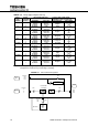
FIGURE 3.2 Diagram of input/output bus bars and terminal blocks
Location of bus bars and terminal blocks (Bottom entry)
Detailed Power Terminals
H=80.6” (2047mm) D=32.8” (832mm)
For power terminals, use 1/2” (12mm) Diameter bolts.
UPS module
160kVA to 225kVA : 35.4” (900mm)
80kVA to 100kVA : 27.6” (700mm)
AC
Input
A
DC
Input
AC Output
Bypass
Input
C
B
A40
C40
B40
A50
C50
B50
BN
BP
Bypass
Input
A40,B40,C40
UPS
module
Battery
Input
BN,BP
AC
Output
A50,B50,C50
AC
Input
A,B,C
Grounding
Bar (E)
External
Block
IOAU-09