
Instruction Manual

G9000 Installation and Operation Manual 13
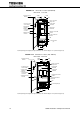
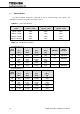
FIGURE 1.5 Display PCB DPAU-81
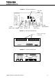
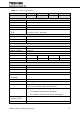
FIGURE 1.6 External I/F PCB IOAU-09
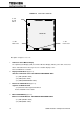
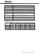
FIGURE 1.7 Parallel I/F PCB IFAU-08
OFF
ON
OFF
ON
IOAU-0
9
TN1
TN2
External contact signal
terminal block
IFAU-0
8A
TLIN
CN96
TLOUT
CN95
CBIN
CBOU
T
CAIN
CAOU
T
CN94
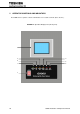
13. SW6
MAINTENANCE
button
12. SW5
TEST switch
START
button
STOP
button
CNV. SW.
switch
11. SW1
RESET switch