
Instruction Manual


Gamatronic Electronic Industries Ltd.
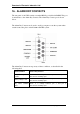
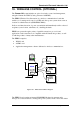
20. CONFIGURING THE POWER+ SA FOR 2- AND 3-PHASE USAGE
Your POWER
+
SA UPS can be configured to operate with 2- or 3-phase input and output. The electrical details for the various possibilities are
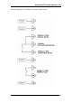
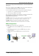
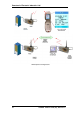
shown in Table 20-1. A cable connection diagram for 2- and 3-phase operation is shown in Figure 20-1. Detailed instructions for 2-phase wiring are
in section 20.1.
Table 20-1: 2- and 3-phase configuration – electrical details
PHASES
(IN/OUT)
INPUT
VOLTAGE
OUTPUT
VOLTAGE
INPUT
CURRENTS
OUTPUT
POWER
INPUT WIRING
OUTPUT WIRING
OUTPUT
CURRENT
OPTION 1
3/3 3x120V+N (3x208V) 3x120V+N (3x208V) 3x23.6 10kVA/8kW L1, L2, L3, N, G L1, L2, L3, N, G 3x28A
OPTION 2
2/2 2x120V+N (1x208V) 2x120V+N (1x208V) 2x26.5 7.5kVA/6kW L1, L2, N, G **[L1+L3], L2, N, G ***2x31A
OPTION 3
2/2 2x120V+N (1x240V) 2x120V+N (1x240V) 2x26.5 7.5kVA/6kW L1, L2, N, G **[L1+L3], L2, N, G 2x31A
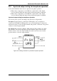
** For output, link terminals L1 and L3 to create phase 1, L2 is phase 2. Both output phases ( [L1+L3] and L2) provide the same current.
*** This value applies when a neutral connection is used.
Figure 20-1: Wiring diagram
POWER
+
SA User Guide (UL), Release 1.0
83