
Instruction Manual


User Guide Gamatronic Electronic Industries Ltd.
15.2.1 Installation Considerations.....................................................................65
15.2.2 Equipment Location ...............................................................................65
15.2.3 Site Connection Diagram .......................................................................65
15.2.4 Elect
r
rical Wiring .....................................................................................66
15.3 Installation Process............................................................................................67
15.3.1 Safety guidelines....................................................................................67
15.3.2 Installing the POWER + SA......................................................................68
15.3.3 Battery installation..................................................................................71
15.4 Verifications Prior to First-Time Operation......................................................73
15.5 First-Time Startup and Verification Test:.........................................................74
16. ALARM DRY CONTACTS .............................................................................................76
17. RS232 INTERFACE .......................................................................................................78
18. SNMP AGENT (OPTIONAL)..........................................................................................79
19. WIRELESS CONTROL (OPTIONAL)............................................................................80
20. CONFIGURING THE POWER+ SA FOR 2- AND 3-PHASE USAGE...........................83
20.1 Input and output wiring for two-phase operation...........................................84
20.1.1 Installing the POWER + SA for 2-phase usage........................................85
21. POWER+ SA SPECIFICATIONS...................................................................................88
LIST OF FIGURES
Figure 2-1: Block Diagram of the POWER+ UPS ..................................................................7
Figure 2-2: Control Panel ........................................................................................................9
Figure 2-3: The LCD screen displays real-time readings ..................................................10
Figure 3-1: Normal Mode display .........................................................................................12
Figure 3-2: Battery Mode display .........................................................................................13
Figure 3-3: Bypass Mode display.........................................................................................14
Figure 4-1: The POWER+ SA control panel.........................................................................15
Figure 4-2: UPS on, Normal mode........................................................................................18
Figure 4-3: Battery test failure..............................................................................................18
Figure 15-1: Site connection block diagram .......................................................................65
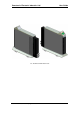
Figure 15-2: UPS rear panel with protective cover.............................................................68
Figure 15-3: UPS rear panel view, with protective cover removed...................................69
Figure 15-4: Batterybox - front right view ...........................................................................71
Figure 15-5: Battery box - front view ....................................................................................71
Figure 15-6: Battery box, front view, front cover removed................................................71
Figure 15-7: Battery box circuit breaker and terminals .....................................................72
Figure 15-8: Battery terminals on the POWER + SA rear panel...........................................72
Figure 19-1: WING General Block Diagram.........................................................................80
Figure 20-1: Wiring diagram ..................................................................................................83
Figure 20-2: Wiring overview for symmetrical 2-phase operation.....................................84
Figure 20-3: UPS rear panel with protective cover.............................................................85
Figure 20-4: UPS rear panel view, with protective cover removed...................................86
iv
POWER
+
SA User Guide (UL), Release 1.7