
Specifications


11921 Slauson Ave. Santa Fe Springs, CA. 90670 (800) 227-4116 FAX (888) 771-7713
33
PATENTS PENDING
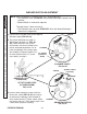
5. When adjustment is com-
plete, tighten the hex nut
and allen head cap screw
on the adjustment block
(FIG. 33-1B). Then
tighten lock nut under
LOWERING switch adjust-
ment screw (FIG. 33-1B)
to hold the setting.
7. Reinstall cover on each tower
(FIG. 33-1A and FIG. 33-2A).
COVER
HEX NUT
LOWERING SWITCH ADJUSTMENT SCREW
FIG. 33-1B
CAP SCREW
(ALLEN HEAD)
INSTALLING COVER
(RH TOWER SHOWN)
FIG. 33-1A
LOCK NUT
(BOTTOM OF
SCREW)
ADJUSTMENT
BLOCK
6. Tighten the hex nut and
allen head cap screw on
the adjustment block (FIG.
33-2B). Then tighten
lock nut under FOLD
switch adjustment screw
(FIG. 33-2B) to hold the
setting.
FOLD SWITCH ADJUSTMENT SCREW
FIG. 33-2B
ADJUSTMENT
BLOCK
HEX NUT
INSTALLING COVER
(LH TOWER SHOWN)
FIG. 33-2A
COVER
ADJUSTMENT
SCREW
ADJUSTMENT
SCREW
LOCK NUT
(BOTTOM OF
SCREW)
CAP SCREW
(ALLEN HEAD)