
Specifications


11921 Slauson Ave. Santa Fe Springs, CA. 90670 (800) 227-4116 FAX (888) 771-7713
24
PATENTS PENDING
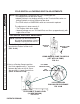
6. Loosen lock nut (FIG. 24-2B) just
enough to turn adjustment screw.
FOLD SWITCH ADJUSTMENT SCREW
FIG. 24-2B
ADJUSTMENT
BLOCK
HEX NUT
REMOVING COVER
(LH TOWER SHOWN)
FIG. 24-2A
CAP SCREW
(ALLEN HEAD)
LIFT TO
REMOVE
COVER
5. Remove cover from tower
(FIG. 24-2A).
LOCK NUT
(BOTTOM OF
SCREW)
ADJUSTMENT
SCREW
SWITCH
ACTUATOR
7. Release the adjustment block (FIG.
24-2B) by loosening hex nut and allen
head cap screw.
NOTE: The FOLD switch adjustment
screw is always on the same
side of the Lift as the Pump
Cover (FIG. 24-1).
RH PUMP
LH PUMP
ADJUSTMENT
SCREW
WHERE TO FIND ADJUSTMENT SCREW
FIG. 24-1
TURNING ADJUSTMENT SCREW
FIG. 24-3
CW TO
ACTIVATE SWITCH
CCW TO
DEACTIVATE SWITCH
8. Turn adjustment screw CW (FIG. 24-
3) until switch just clicks (activates). If
switch is already activated, turn ad-
justment screw CCW until switch just
clicks (deactivates). Then turn screw
CW until it just clicks (activates).
FOLD SWITCH & LOWERING SWITCH ADJUSTMENTS - Continued