
Specifications


11921 Slauson Ave. Santa Fe Springs, CA. 90670 (800) 227-4116 FAX (888) 771-7713
18
PATENTS PENDING
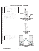
4. To ensure proper leveling, turn
PLATFORM TILT adjustment
screws (FIG. 18-2) an equal
amount, on both sides of Plat-
form. Turn adjustment screws
clockwise (FIG. 18-3) to tilt
the Platform up or counter-
clockwise to tilt Platform down.
PLATFORM TILT ADJUSTMENT SCREW
(RH SIDE OF PLATFORM SHOWN)
FIG. 18-2
PLATFORM TILT ADJUSTMENT SCREWS
FIG. 18-3
CW - TILT
PLATFORM UP
CCW - TILT
PLATFORM DOWN
PLATFORM
ADJUSTMENT
SCREW
(2 PLACES)
INBOARD
ROLLSTOP
(REF)
PLATFORM TILT ADJUSTMENT - Continued
PLATFORM LOWERED TO GROUND LEVEL
FIG. 18-1
PLATFORM
GROUND
LEVEL
ILLUMINATED
POWER
SWITCH
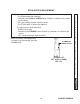
2. Measure distance from
front of the Platform (1) to
the ground (FIG. 18-1).
Next measure the distance
from the bottom of the Vertical
Arm (2) to the ground
(FIG. 18-1).
3. The measurement at the Vertical
Arm (2) must be 1/2” -1” higher
than the measurement at the
front of Platform (1). For ex-
ample: If you measure 4” at the
front (1), then you should mea-
sure from 4-1/2” to 5” at the Ver-
tical Arm (2). If there is not a 1/2”
- 1” difference, do instruction 4
to get the correct measurement.
(2)
(1)
VERTICAL
ARM