
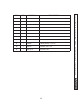
Specifications
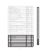

39
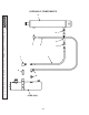
11921 Slauson Ave. Santa Fe Springs, CA. 90670 (800) 227-4116 FAX (888) 771-7713
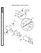
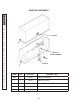
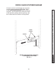
DRIVE CHAIN SYSTEM DIAGRAM
If the drive chains or related parts are removed,
route the chains as shown in FIG. 39-1. Refer
to the PARTS BREAKDOWN section for the cor-
rect parts. The illustration also shows the motion
of the hydraulic cylinder, sheaves (pulleys), and
drive chains while the Platform is being raised.
DRIVE CHAIN ROUTING & MOTION
FOR RAISING PLATFORM
FIG. 39-1
CYLINDER
DRIVE
CHAINS
SHEAVE