
Installation manual

28
11921 Slauson Ave. Santa Fe Springs, CA. 90670 (800) 227-4116 FAX (888) 771-7713
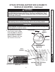
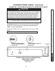
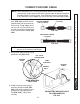
2. On the bare wire end of fused power cable, keep enough length to attach copper ter-
minal lug and reach motor solenoid without putting tension on cable (after connection)
(FIG. 28-1A). Measure (if needed), and then cut excess cable from bare wire end of
cable. Put heatshrink tubing (Parts Box item) (FIG. 28-1B) on the end of the cable and
leave room for terminal lug. Crimp copper terminal lug (5/16” ring, Parts Box item) on
the fused power cable and shrink the heatshrink tubing (FIG. 28-1C).
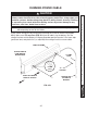
CONNECT POWER CABLE
TYPICAL FUSED POWER CABLE ROUTING
FIG. 28-1A
FIG. 28-1B
COPPER
TERMINAL
LUG
HEATSHRINK
TUBING
FIG. 28-1C
FUSED
POWER CABLE
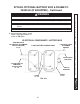
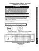
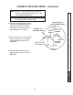
CONNECTING POWER CABLE TO
PUMP STARTER SWITCH
FIG. 28-2
FUSED
POWER CABLE
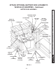
3. Remove hex nut and lock washer
from battery power terminal on
the starter solenoid. Connect the
fused power cable to the starter
switch as shown in FIG. 28-2.
Reinstall and tighten lock washer
and hex nut.
NOTE: MAXON recommends using
dielectric grease on all electri-
cal connections.
Do not over-tighten the terminal nuts on
starter switch. For the load terminals, torque
nuts to 40 lb.-in. max. Torque the nuts on #10-
32 control terminals 15-20 lb.-in.
CAUTION
NOTE: Do not remove fl at washer from
the battery power terminal.
STARTER
SWITCH
NUT & LOCK
WASHER
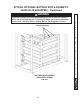
1. Run power cable through hole in pump
box wall (FIG. 28-1A).