M-91-17 REV. D DECEMBER 2010 INSTALLATION MANUAL RCM-1250 C RCM-1250 C AB RCM-1600 RCM-1600 C AB LIFT CORP. © MAXON Lift Corp.
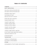
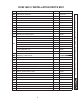
TABLE OF CONTENTS WARNINGS ........................................................................................................................... 3 SAFETY INSTRUCTIONS .................................................................................................... 3 RCM-1250 C INSTALLATION PARTS BOX ......................................................................... 4 RCM-1600 C INSTALLATION PARTS BOX .........................................................................
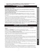
Comply with the following WARNINGS and SAFETY INSTRUCTIONS while installing Liftgates. See Operation Manual for operating safety requirements. ! WARNING • Do not stand, or allow obstructions, under the platform when lowering the Liftgate. Be sure your feet are clear of the Liftgate. • Keep fingers, hands, arms, legs, and feet clear of moving Liftgate parts (and platform edges) when operating the Liftgate. • Correctly stow platform when not in use.
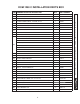
RCM-1250 C INSTALLATION PARTS BOX REF PARTS BOX, RCM-1250C QTY PART NUMBER 1 251813-01 1 FRAME CLIP, 1/2” X 1-3/8” 7 050079 2 TAPPING SCREW, #10 x 1/2” LG. 4 030458 3 FUSED POWER CABLE, 175 AMP, 38’ LG. 1 264422 4 JIFFY CLAMP, #130 1 125674 5 BUTT CONNECTOR, 14AWG 1 030491 6 FLAT WASHER, 3/8” 2 030556 7 BRASS ELBOW, 1/4” X 1” LG. 1 202406 8 LOOM CLAMP, #8 RUBBER 3 214663 9 ELBOW, 3/8” FEM-3/8” FEM 1 228950 PUMP BOX KIT (RCM) 1 251738-02 A.
RCM-1600 C INSTALLATION PARTS BOX REF PARTS BOX, RCM-16C QTY PART NUMBER 1 251814-01 1 FRAME CLIP, 1/2” X 1-3/8” 7 050079 2 TAPPING SCREW, #10 x 1/2” LG. 4 030458 3 FUSED POWER CABLE, 175 AMP, 38’ LG. 1 264422 4 JIFFY CLAMP, #130 1 125674 5 BUTT CONNECTOR, 14AWG 1 030491 6 FLAT WASHER, 3/8” 2 030556 7 BRASS ELBOW, 1/4” X 1” LG. 1 202406 8 LOOM CLAMP, #8 RUBBER 3 214663 9 ELBOW, 3/8” FEM-3/8” FEM 1 228950 PUMP BOX KIT (RCM) 1 251738-02 A.
11921 Slauson Ave. Santa Fe Springs, CA.
11921 Slauson Ave. Santa Fe Springs, CA.
11921 Slauson Ave. Santa Fe Springs, CA.
11921 Slauson Ave. Santa Fe Springs, CA.
11921 Slauson Ave. Santa Fe Springs, CA.
921 Slauson Ave. Santa Fe Springs, CA.
11921 Slauson Ave. Santa Fe Springs, CA.
11921 Slauson Ave. Santa Fe Springs, CA.
11921 Slauson Ave. Santa Fe Springs, CA.
11921 Slauson Ave. Santa Fe Springs, CA.
11921 Slauson Ave. Santa Fe Springs, CA.
INSTALLING PUMP & PUMP BOX PUMP PUMP BOX PUMP MOUNT 1/4” 2 PLACES PUMP MOUNT 13/16” 10-7/8” 3-3/4” 251817 MOUNT BRACKET 17 11921 Slauson Ave. Santa Fe Springs, CA.
INSTALLING PUMP & PUMP BOX - Continued 251681 COVER 251741 PUMP BOX ASSY PUMP ASSY (REF) 251680 BOX BOLT 3/8”-16 X 1-1/4” LG PUMP MOUNT (REF) 3/8” LOCK WASHERS (2 PLACES) MOUNT BRACKET (REF) 3/8” LOCK WASHERS (2 PLACES) 3/8” FLAT WASHERS (2 PLACES) 3/8”-16 HEX NUT (2 PLACES) 18 BOLT 3/8”-16 X 1” LG (2 PLACES) 11921 Slauson Ave. Santa Fe Springs, CA.
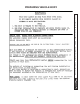
RUNNING POWER CABLE CAUTION Never route an energized wire. Make sure the vehicle battery is disconnected. Always route electrical wires clear of moving parts, brake lines, sharp edges and exhaust systems. Avoid making sharp bends in wiring. Attach securely. If drilling is necessary, first check behind the drilling surface to prevent damage to any fuel lines, vent lines, brake lines or wires.
CONNECT POWER CABLE 2. On the bare wire end of fused power cable, keep enough length to attach copper terminal lug and reach motor solenoid without putting tension on cable (after connection) (FIG. 20-2A). Measure (if needed), and then cut excess cable from bare wire end of cable. Put heatshrink tubing (Parts Box item) (FIG. 20-2B) on the end of the cable and leave room for terminal lug. Crimp copper terminal lug (5/16” ring, Parts Box item) on the fused power cable and shrink the heatshrink tubing (FIG.
NOTE: To ensure power unit is correctly grounded, MAXON recommends connecting 2 gauge ground cable from grounding bolt on pump manifold to grounding point on vehicle frame. Use remaining length of 2 guage cable (Parts Box item) and 2 copper lugs (Parts Box item) to make ground cable. 1. Put heatshrink tubing (Parts Box item) (FIG. 21-1) on each end of ground cable and leave room for terminal lug.
NOTE: If there is a grounding point on the frame, use it to connect ground cable. Then, skip the step for drilling a hole. NOTE: Clean the ground cable connection point on the frame down to bare metal. 4. Extend the ground cable to reach vehicle frame (FIG. 22-1) without putting tension on cable (after connection). Connect to existing grounding point if available. 5. If necessary, drill a 11/32” (0.343”) hole in vehicle frame for bolting the ground cable terminal lug (FIG. 22-1).
11921 Slauson Ave. Santa Fe Springs, CA.
11921 Slauson Ave. Santa Fe Springs, CA.
1. Extend the control switch cable through hole in pump box wall (FIG. 25-1). Connect 3 control wires to solenoid valve and starter switch (FIG. 25-1). Ensure wiring has slack after connections are made. BLACK (SOL. VALVE) BUTT CONNECTOR GROUND CABLE (REF) GREEN (BATTERY+) WHITE (START SWITCH COIL+) POWER CABLE (REF) CONNECTING CONTROL SWITCH CABLE TO PUMP ASSEMBLY FIG. 25-1 2. Connect 3 control wires to solenoid valve and starter switch as follows (FIG. 25-1).
CONNECT RETURN HOSE ELBOW (1/4” X 1/4”) PLASTIC HOSE (1/4” O.D.) RESERVOIR BUSHING (3/8” TO 1/4”) RETURN PORT RETURN HOSE CONNECTED TO PUMP RESERVOIR FIG. 26-1 NOTE: Apply thread sealant (Parts Box item) to hydraulic line connections. 2. Connect bushing and 1/4” x 1/4” elbow (Parts Box items) to return port on reservoir (FIG. 26-1). 3. Connect return hose to elbow (FIG. 26-1). 26 11921 Slauson Ave. Santa Fe Springs, CA. 90670 (800) 227-4116 FAX (888) 771-7713 1.
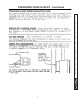
CONNECT POWER CABLE TO BATTERY Remove nut from positive (+) battery terminal connector. Connect power cable to the positive (+) battery terminal connector (FIG. 27-1). Reinstall and tighten nut. POSITIVE (+) BATTERY TERMINAL FUSED POWER CABLE BOLT NUT CONNECTING POWER CABLE FIG. 27-1 27 11921 Slauson Ave. Santa Fe Springs, CA. 90670 (800) 227-4116 FAX (888) 771-7713 NOTE: MAXON recommends using dielectric grease on all electrical connections.
NOTE: To set pressure relief valve, hydraulic pressure gauge must be connected to lifting port on pump manifold. Do the pump pressure relief valve adjustment before connecting pressure hose from cylinder. 1. Remove shipping plug from pressure port on pump manifold (FIG. 28-1). Then, connect 5000 psi pressure gauge to pressure port. PRESSURE GAUGE PRESSURE PORT MANIFOLD RELIEF VALVE ADJUSTMENT ADJUSTING PRESSURE RELIEF VALVE FIG. 28-1 2. Remove relief valve cover from manifold (FIG. 28-1). 3.
CONNECT PRESSURE LINE 1. Connect pipe nipple and swivel elbow (Parts Box items) to pressure port on pump manifold (FIG. 29-1). SWIVEL PRESSURE HOSE ELBOW 2” LG PIPE NIPPLE MANIFOLD PRESSURE PORT PRESSURE HOSE CONNECTED TO PUMP MANIFOLD FIG. 29-1 2. Connect pressure hose to swivel end of pipe nipple (FIG. 29-1). 29 11921 Slauson Ave. Santa Fe Springs, CA. 90670 (800) 227-4116 FAX (888) 771-7713 NOTE: Apply thread sealant (Parts Box item) to hydraulic line connections.
NOTE: Vehicle body must be empty (unloaded) before performing the following adjustment. 1. Adjust drive chains as follows. ADJUSTING RODS ADJUSTING NUTS CYLINDER LOCK NUTS 2. Remove cover from Cylinder Housing. Loosen the lock nut on each chain adjusting rod (FIG. 30-1). Then lower Platform to ground level. 3. Turn each chain adjusting nut (FIG. 30-1) an equal amount of clockwise turns (alternate from chain to chain) until hydraulic cylinder is fully compressed. Then tighten the lock nut (FIG.
CHECKING HYDRAULIC FLUID Keep dirt, water and other contaminants from entering the hydraulic system. Before opening the hydraulic fluid reservoir filler cap, drain plug and hydraulic lines, clean up contaminants that can get in the openings. Also, protect the openings from accidental contamination. NOTE: Use correct grade of hydraulic fluid for your location. +50 to +120 Degrees F - Grade ISO 32 Below + 70 Degrees F - Grade ISO 15 or MIL-H-5606 See TABLES 23-1 and 23-2 for recommended brands.
ISO 32 HYDRAULIC OIL RECOMMENDED BRANDS PART NUMBER AMSOIL AWH-05 CHEVRON HIPERSYN 32 KENDALL GOLDEN MV SHELL TELLUS T-32 EXXON UNIVIS N-32 MOBIL DTE-13M, DTE-24, HYDRAULIC OIL-13 TABLE 32-1 ISO 15 OR MIL-H-5606 HYDRAULIC OIL RECOMMENDED BRANDS PART NUMBER AMSOIL AWF-05 CHEVRON FLUID A, AW-MV-15 KENDALL GLACIAL BLU SHELL TELLUS T-15 EXXON UNIVIS HVI-13 MOBIL DTE-11M ROSEMEAD THS FLUID 17111 TABLE 32-2 32 11921 Slauson Ave. Santa Fe Springs, CA.
CONTROL SWITCH DECAL P/N 250993 CAPACITY DECAL (RCM-1600 ONLY) P/N 224751 CAPACITY DECAL (RCM-1250 ONLY) P/N 226006 WARNING DECAL P/N 264081 INSTRUCTION DECAL P/N 252899 33 11921 Slauson Ave. Santa Fe Springs, CA.
TOUCHUP PAINT Damaged cylinder seals and contaminated hydraulic fluid can result from painting the polished portion of the cylinder rod. To prevent damage, protect the exposed polished portion of the cylinder rod while painting. If bare metal or primer is exposed on the painted portions of the Liftgate, touch up the paint. To maintain the protection provided by the original paint system, MAXON recommends aluminum primer touchup paint kit, P/N 908134-01. 34 11921 Slauson Ave. Santa Fe Springs, CA.
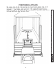
HYDRAULIC CYLINDER 2 GPM FLOW CONTROL VALVE AUX. TANK PORT (PLUGGED) VENT PORT PRESSURE PORT “A” VALVE CHECK VALVE PRESSURE RELIEF VALVE (SET AT 3250 PSI) HAND PUMP PORT (PLUGGED) PUMP MOTOR (REF) FILTER 35 HAND PUMP PORT (PLUGGED) 11921 Slauson Ave. Santa Fe Springs, CA.
CONTROL SWITCH WHITE GREEN BLACK CABLE ASSY STARTER SOLENOID SOLENOID, VALVE “A” BLACK MOTOR CABLE WITH 175 AMP FUSE BATTERY 36 11921 Slauson Ave. Santa Fe Springs, CA.
MISCELLANEOUS KITS PART NO.
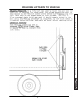
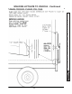
NOTE: Make sure the Liftgate power unit, and all batteries on the vehicle for the power unit, are connected correctly to a common chassis ground. 1. Liftgate and additional battery box are typically installed on trailers as shown in FIG. 38-1 and on trucks as shown in FIG. 38-2. See the following page for battery and cable connections.
NOTE: Always connect fused end of power cable to battery positive (+) terminal. 2. Recommended battery box setup for 6 volt batteries is shown in FIG. 39-1. (+) BATTERY CABLES 150 AMP CIRCUIT BREAKER (NEAR TRUCK OR 150 AMP CIRCUIT TRACTOR BATTERY AND/OR BREAKER NOSE OF TRAILER) 200 AMP FUSED POWER CABLE (ONLY IF REQUIRED - SEE NOTE) CHARGE LINE TO TRUCK OR TRACTOR BATTERY POWER CABLE TO PUMP BOX (-) BATTERY CABLE 6 VOLT BATTERY CONNECTIONS FIG.
NOTE: Always connect fused end of power cable to battery positive (+) terminal. 4. Recommended battery box setup for getting +24 volt dc power from 12 volt batteries is shown in FIG. 40-1. (+) BATTERY CABLES 150 AMP CIRCUIT BREAKER 150 AMP CIRCUIT BREAKER (NEAR TRUCK OR TRACTOR BATTERY AND/OR NOSE OF TRAILER) 200 AMP FUSED POWER CABLE (ONLY IF REQUIRED - SEE NOTE) CHARGE LINE TO TRUCK OR TRACTOR BATTERY POWER CABLE TO PUMP BOX (-) BATTERY CABLE 12 VOLT BATTERY CONNECTIONS FOR +24 VDC POWER FIG.