
Specifications

11921 Slauson Ave. Santa Fe Springs, CA. 90670 (800) 227-4116 FAX (888) 771-7713
14
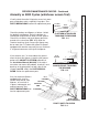
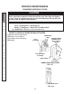
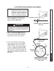
CAUTION
Pump cover must be correctly se-
cured to prevent it from becoming
a hazard. To secure pump cover,
the long side of the holder fl ats
must butt against pump cover as
shown in the illustration.
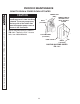
1. Unbolt and remove pump cover
(FIG. 14-1).
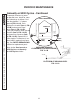
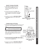
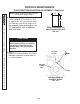
CHECKING HYDRAULIC FLUID
3. If needed, add fl uid to the reservoir as
follows. Pull out (no threads) fi ller cap
(FIG. 14-2). Fill the reservoir with hy-
draulic fl uid to level shown in FIG. 14-
2. Reinstall fi ller cap (FIG. 14-2).
4. Bolt on the pump cover as shown in
FIG. 14-1. Torque the 5/16”-18 cover
bolts from 10 to 14 lbs.-ft.
2. Check the hydraulic fl uid level in
reservoir as follows. With Liftgate
stowed, or platform at vehicle bed
height, level should be as shown in
FIG. 14-2.
NOTE: If the hydraulic fl uid in the
reservoir is contaminated, do
the CHANGING HYDRAULIC
FLUID procedure in this section.
PERIODIC MAINTENANCE
UNBOLTING / BOLTING PUMP COVER
FIG. 14-1
POWER UNIT FLUID LEVEL
FIG. 14-2
2”
FILLER
CAP
RESERVOIR
PUMP COVER
BOLTS
(2 PLACES)
POWER UNIT
(REF)
FLAT WASHERS
(2 PLACES)
NUTS
(2 PLACES)
LONGER SIDE OF
HOLDER FLATS
BUTT AGAINST
COVER
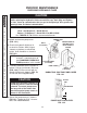
CAUTION
Keep dirt, water and other contaminants from entering the hydraulic system.
Before opening the hydraulic fl uid reservoir fi ller cap, drain plug and hydrau-
lic lines, clean up contaminants that can get in the openings. Also, protect the
openings from accidental contamination.
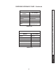
+50 to +120 Degrees F - Grade ISO 32
Below + 70 Degrees F - Grade ISO 15 or MIL-H-5606
NOTE: Use correct grade of hydraulic fl uid for your location.
See TABLES 15-1 & 15-2 for recommended brands.