
Specifications

11921 Slauson Ave. Santa Fe Springs, CA. 90670 (800) 227-4116 FAX (888) 771-7713
11
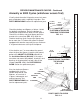
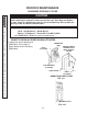
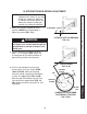
Check the platform and fl ipover as follows. Unfold
the platform and fl ipover. Raise the platform to
vehicle bed height and then lower it to the ground.
Check if the shackles and tip of fl ipover touch the
ground at the same time (FIG. 11-1). With the
shackles touching, tip of a ramp-style fl ipover may
be no more than 1/4” above the ground. A fl ipover
equipped with retention ramp may have a maximum
2” of ground clearance at the tip of the fl ipover.
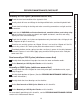
Visually check the entire Liftgate for excessively worn
parts and broken welds, especially hinge pins. See
PARTS BREAKDOWN section for replacement parts.
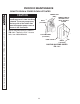
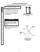
Annually or 5000 Cycles (whichever occurs fi rst)
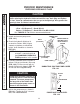
LIFT ARM
PARALLEL
ARM
LIFT
CYLINDER
PLATFORM
PIVOT POINTS
(PINS & BEARINGS)
PIVOT POINTS TO CHECK
FIG. 11-3
Also, for aluminum fl ipovers
equipped with single re-
tention ramp and for steel
fl ipovers, ensure latch is
in place, undamaged, and
working correctly. See
PARTS BREAKDOWN
sec-
tion for replacement parts.
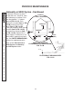
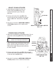
SHACKLES NOT TOUCHING
THE GROUND
FIG. 11-2
PLATFORM & SHACKLES
TOUCHING THE GROUND
FIG. 11-1
If the shackles are 1” or more above the ground
when the tip of the fl ipover is touching the ground,
perform the ADJUST PLATFORM procedure in
the Installation Manual (M-04-06). If the adjust-
ment does not correct the problem, check pins and
bearings at the pivot points on both sides of the
Liftgate (see FIG. 11-3). See PARTS BREAK-
DOWN section for replacement parts.
T I P O F
STANDARD
FLIPOVER
1/4” (MAX.)
(SEE NOTE)
SHACKLE
1”
(OR MORE)
TIP OF
FLIPOVER
SHACKLE
PERIODIC MAINTENANCE CHECKS - Continued