
Installation Instructions
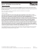

General Wiring Diagram
CAUTION: Turn off electrical power at fuse or circuit breaker box before wiring fixture to the power supply. Note that the fixtures are supplied with two
105°C leads. The white lead is to be connected to the neutral and the black lead to the power (line) lead. Attach ground wire to junction box “GRD” by
means of green screw. Grounding for fixture is by means of attaching wire to “GRD” on fitter backing using green screw provided. Make all wiring
connections in accordance to local electrical code.
Installation & Operation
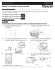
1. Drill three appropriate mounting holes into
the mounting surface/wall according to
below diagram.
Disconnect the power by turning off the circuit breaker or by removing the appropriate fuse at the
fuse box. Turning the power off using the light switch is not sufficient to prevent electrical shock.
2. Loosen 2 door screws by using an Allen key (A),
disconnect the connector (B).
3. Loosen safety cable and take off the front door. If there's
any conduit for the fixture installation, use a cross head
Philips slot screwdriver to remove appropriate ½” plug.
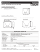
4. Feed supply wires through Junction Box, make sure
the Gasket is fully sealed. Secure the fixture to solid
surface. Use leveling bubble to level fixture.
5. Attach the front door and safety cable to housing. 6. Connect power cord to supply wires using UL listed
wire connectors. Plug connectors on the input and
output ends.
© Copyright 2017. MaxLite, Inc. All Rights Reserved.
12 York Ave, West Caldwell, NJ 07006 Tel: 800-555-5629 Fax: 973-244-7333 Email: info@maxlite.com
Page: 2
REV: 02/20/17
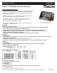
Operating Instructions WP-WMP Series
MaxLite LED WallMax Precision Wall Pack
®