
Installation Instructions

Installation & Operation - Double-Ended Wiring
Disconnect the power by turning off the circuit breaker or by removing the appropriate fuse at the
fuse box. Turning the power off using the light switch is not sufficient to prevent electrical shock.
Step 1: Make sure the circuit breaker that supplies power to the fixture is turned off.
Step 2: Remove lens or diffusion cover on the lighting fixture.
Step 3: Remove the existing T8/T12 fluorescent tubes.
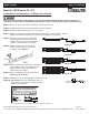
Step 4: Remove the ballast cover and identify the line and neutral wires running from the breaker
box to the ballast and confirm the power is off using a voltmeter.
Step 5: Cut the line and neutral wires at the ballast,
as well as all remaining wires at the ballast
(see Figure 1).
Step 6: Remove Ballast (and starter if present).
Dispose of removed ballast in accordance
with government regulations in your area.
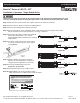
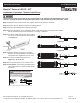
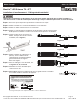
Step 7: For single-ended wiring, please see
Figure 3a, 3b, 3c or 3d.
Step 8: Reinstall the ballast cover to hide all wire.
Step 9: IMPORTANT: Peel off the provided caution
label and install on a visible location inside
the fixture.
Label pictures are for illustration purposes only.
- Black
+ Red
Driver
0~10V Dimming
+
-
Purple
Gray
~
L N
AC
- Black
+ Red
Driver
0~10V Dimming
+
-
Purple
Gray
~
L N
AC
- Black
+ Red
Driver
0~10V Dimming
+
-
Purple
Gray
~
L N
AC
- Black
+ Red
Driver
0~10V Dimming
+
-
Purple
G
ray
~
L N
AC
Figure 3a
Figure 3b
Figure 3c
Figure 3d
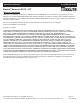
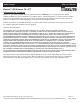
Kit Model:
L11.5T8EX4xxDDR1L11
Lamp Model: L11.5T8EX4xx “xx” = CCT: 35, 40, 50 or 65
- Black
+ Red
Driver
0~10V Dimming
+
-
Purple
Gray
~
L N
AC
- Black
+ Red
Driver
0~10V Dimming
+
-
Purple
Gray
~
L N
AC
Operating Instructions L11.5T8EX4xx Series
MaxLite External LED T8 - 4FT
®
© Copyright 2019. MaxLite, Inc. All Rights Reserved.
12 York Ave, West Caldwell, NJ 07006 Tel: 800-555-5629 Fax: 973-244-7333 Email: info@maxlite.com
Page: 3
REV: 1/03/19