
Specification Sheet

Phone: 1-800-555-5629 | Fax: 973-244-7333 | Web: www.maxlite.com | E-mail: info@maxlite.com
MAX18010
Revised: 10/09/18
LED HIGH BAY LINEAR
ECONOMICAL SERIES
Page: 4 of 5
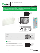
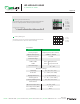
LED Driver
Note: this 1-10V output is isolated, SELV output. Do not connect the 1-10V terminals on driver X to Driver Y.
L
L L’
N
N N
+
1-10V
1-10V
LED
+
+
L N
+
Wiring Diagram
Stand-by dimming level
Detection range
ON/
OFF
Auto Mode
Reset
Power
80%
Test
2s
10%
20%
30s 1min
100%
30min10min5min
0s 10s 1min
30%
SC1 SC2
SC3
Scene mode
10min
50% 10%
30min
Hold-time
Stand-by period
5min
Lux
Disable
2Lux
10Lux
50Lux
Daylight Sensor
SC4
Power
100%
+
-
Dim
M/A
Note: the buzzer beeps one time
when RC receives signal
successfully.
Ceiling mounted height (m)
10%
30%
75%
50%
Hytronik Microwave motion sensor
65
I – Disable
II – 50Lux
III – 10Lux
IV – 2Lux
Disable
50Lux
10Lux
2Lux
1 2
0s
10s
1min
5min
10min
30min
1H
+
2 31
I – 10%
II – 20%
III – 30%
IV – 50%
I – 0s
II – 10s
III – 1min
IV – 5min
V – 10min
VI – 30min
VII – 1H
VIII –
∞
+
I – 100%
II – 75%
III – 50%
IV – 10%
I – 5s
II – 30s
III – 1min
IV – 5min
V – 10min
VI – 20min
VII – 30min
100%
75%
50%
10%
5s
30s
1min
5min
10min
20min
30min
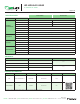
1 Detection Range
2 Hold-time
3 Daylight Threshold
Sensor sensitivity can be adjusted by selecting the combination on the DIP
Select the dip switch configuration for the full brightness on-time after presense
detection.
Please note that this function is disabled when the natural daylight exceeds the
daylight threshold setting for more than 5 minutes.
1 2
2 31
5 Stand-by dimming level
4 Stand-by period (corridor function)
This is the time period you would like to keep at the low light output level
before it is completely switched o in the long absence of people.
The setting is used to select the desired dimmed light level used in
periods of absence for enhanced comfort and safety.
10%
20%
30%
50%
1 2
Note: “0s” means on/o control;
ambient lux level exceeds the daylight threshold preset.
Please note that the ambient lux level refers to internal light reaching the sensor.
Disabling the daylight sensor will put the sensor into occupancy detection only mode.
www.hytronik.com
Below are all available settings for the MS (motion sensor) option. Default
settings are highlighted in green. To change the default settings, purchase of
the remote control (RMHYTHRC-05) is required.
Hytronik Microwave motion sensor
65
I – Disable
II – 50Lux
III – 10Lux
IV – 2Lux
Disable
50Lux
10Lux
2Lux
1 2
0s
10s
1min
5min
10min
30min
1H
+
2 31
I – 10%
II – 20%
III – 30%
IV – 50%
I – 0s
II – 10s
III – 1min
IV – 5min
V – 10min
VI – 30min
VII – 1H
VIII –
∞
+
I – 100%
II – 75%
III – 50%
IV – 10%
I – 5s
II – 30s
III – 1min
IV – 5min
V – 10min
VI – 20min
VII – 30min
100%
75%
50%
10%
5s
30s
1min
5min
10min
20min
30min
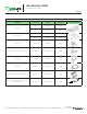
1 Detection Range
2 Hold-time
3 Daylight Threshold
Sensor sensitivity can be adjusted by selecting the combination on the DIP
Select the dip switch configuration for the full brightness on-time after presense
detection.
Please note that this function is disabled when the natural daylight exceeds the
daylight threshold setting for more than 5 minutes.
1 2
2 31
5 Stand-by dimming level
4 Stand-by period (corridor function)
This is the time period you would like to keep at the low light output level
before it is completely switched o in the long absence of people.
The setting is used to select the desired dimmed light level used in
periods of absence for enhanced comfort and safety.
10%
20%
30%
50%
1 2
Note: “0s” means on/o control;
ambient lux level exceeds the daylight threshold preset.
Please note that the ambient lux level refers to internal light reaching the sensor.
Disabling the daylight sensor will put the sensor into occupancy detection only mode.
www.hytronik.com
Below are all available settings for the MS (motion sensor) option. Default
settings are highlighted in green. To change the default settings, purchase of
the remote control (RMHYTHRC-05) is required.