
Manual


3
Capacities and Pressure Drop
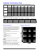
Pressure Drop Chart
Sizing Instructions
Pressure Drop ( P)
When 325 Series regulators are used on 2 psig piping systems -
often times the 2 psig residential systems are sized with a 1-1/2
psi pressure drop through the copper or stainless steel tubing.
This means there will be 2 psi at the inlet of the regulator under
no flow conditions, and 1/2 psi at the regulator inlet under
maximum flow conditions.
To select a 325 series appliance regulator of ample flow - one
must know:
1. Available inlet pressure (maximum static/minimum
operating).
2. Desired outlet pressure.
3. Required maximum flow rate.
4. Pipe size.
Example: To select a 325 series regulator of ample capacity to
handle flow. . .
KNOWN:
Desired flow rate 145 CFH; pipe size 1/2"; operating inlet
pressure 2 psi; outlet pressure 7" w.c.; lockup required.
SOLUTION:
Check pressure drop chart above - the 325-3's pressure drop at
a flow rate of 145 CFH is 7" w.c. - well below the available
differential of 1.75 psi. The 325-3 (1/2") used with a 4" to 12"
spring, set at 7", is the correct regulator to use for this application.
*NOTE: Maximum Individual Load: 325-3 is 100 CFH (2.8 m
3
/h), 325-5A is 250 CFH (7.0 m
3
/h), 325-7 is 900 CFH (25.5 m
3
/h)
Approval based on use as an appliance regulator.
CAPACITIES - based on 1" w.c. pressure drop, from set point
*
. 0.64 sp gr gas expressed in CFH (m
3
/h).
PRESSURE DROP - 0.64 sp gr gas expressed in CFH (m
3
/h) (for system pressure drop calculations)
Model Number
Outlet
Pressure
Set Point
CSA
Max.
CFH
1/2 psi
(34 mbar)
3/4 psi
(52 mbar)
1 psi
(69 mbar)
2 psi
(138 mbar)
5 psi
(345 mbar)
10 psi
(690 mbar)
325-3*
325-5A*
325-7
4.0” w.c.
150
160 (4.5) 190 (5.4) 220 (6.2) 220 (6.2) 300 (8.5) 320 (9.1)
7.0” w.c.
150
120 (3.4) 150 (4.2) 180 (5.1) 220 (6.2) 290 (8.2) 320 (9.1)
10.0” w.c.
150
100 (2.8) 120 (3.4) 150 (4.2) 220 (6.2) 280 (7.9) 320 (9.1)
4.0” w.c.
300
300 (8.5) 340 (9.6) 416 (11.8) 500 (14.2) 600 (17.0) 680 (19.3)
7.0” w.c.
300
245 (6.9) 315 (8.9) 340 (9.6) 480 (13.6) 600 (17.0) 680 (19.3)
10.0” w.c.
300
225 (6.4) 270 (7.6) 312 (8.8) 430 (12.2) 560 (15.9) 680 (19.3)
4.0” w.c.
-
670 (19.0) 900 (25.5) 1050 (29.7) 1450 (41.1) 1750 (49.6) 2000 (56.6)
7.0” w.c.
-
590 (16.7) 760 (21.5) 900 (25.5) 1250 (35.4) 1750 (49.6) 2000 (56.6)
10.0” w.c.
-
470 (13.3) 650 (18.4) 800 (22.7) 1250 (35.4) 1750 (49.6) 2000 (56.6)
Operating Inlet Pressure
© 2008, Maxitrol Company, All Rights Reserved
Model
7.0” w.c. (17 mbar)
1/2 psi (34 mbar)
3/4 psi (52 mbar)
1 psi (69 mbar)
2 psi (138 mbar)
325-3
325-5A
325-7
145 (4.0) 204 (5.8)
250 (7.0)
289 (8.2)
-
338 (9.6)
476 (13.5)
583 (16.5) 673 (19.1)
-
690 (19.5) 972 (27.6)
1191 (33.8)
1375 (39.0)
1975 (55.9)