
Installation Guide

Maximal3V / Maximal5V / Maximal7V Access Power Controllers (Fused) Installation Guide - 9 -
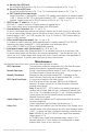
+ BAT -
L G N BAT FAIL NC C NO NC C NO AC FAIL
AC
DC
- DC +
OUTPUT 1 OUTPUT 2 OUTPUT 3 OUTPUT 4 OUTPUT 5 OUTPUT 6 OUTPUT 7 OUTPUT 8
NC C NO COM NC C NO COM NC C NO COM NC C NO COM NC C NO COM NC C NO COM NC C NO COM NC C NO COM
IN GND IN GND IN GND IN GNDIN GND IN GND IN GND IN GND
1 2 3 4
5 6 7 8
INPUT
TRIGGER
10A 250V
+INP- T + RET-
NO C NC
FACP INTERFACE
Power Control
- + - +
F1 F2 F3 F4 F5 F6 F7 F8
MAIN
TRG
FACP
1 2 3 4
1 2 3 4
ON
ON
1 2 3 4
1 2 3 4
ON
ON
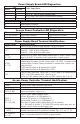
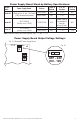
Optional
Rechargeable
Stand-by Battery
Optional
Rechargeable
Stand-by Battery
Optional
Rechargeable
Stand-by Battery
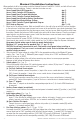
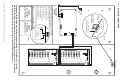
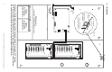
CAUTION: When power supply board is set for 12VDC
use only one (1) 12VDC stand-by battery.
Connect red battery lead to
the terminal marked [+ BAT]
and to the [positive (+)]
terminal of the battery.
Connect black battery lead to
terminal marked [BAT –]
and to the [negative (–)]
terminal of the battery.
- BAT +
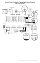
Input 220VAC
50/60Hz
Line Neutral
Tamper Switch
Keep power-limited wiring separate from non power-limited. Use minimum 0.25” spacing.
Up to four (4) 12AH rechargeable batteries are the largest batteries that can fit in this enclosure.
An external battery enclosure must be used if using the 40AH or 65AH batteries.
Ground
Lug
Fig. 3 - Maximal3V and Maximal5V
Fig. 3a
Fig. 3b
Tamper Switch
(not included)
To Access Control Panel or
UL Listed Reporting Device
Edge of
Enclosure
Enclosure