
Installation Guide

- 6 - Maximal3V / Maximal5V / Maximal7V Access Power Controllers (Fused) Installation Guide
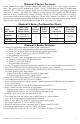
Power Supply Board LED Diagnostics:
LED
Power Supply Status
Red (DC) Green (AC)
ON ON Normal operating condition.
ON OFF Loss of AC. Stand-by battery supplying power.
OFF ON No DC output. Short circuit or thermal overload condition.
OFF OFF No DC output. Loss of AC. Discharged battery.
Red (Bat) Battery Status
ON Normal operating condition.
OFF Battery fail/low battery.
Access Power Controller LED Diagnostics:
LED ON OFF
LED 1- LED 8 (Red) Output relay(s) energized. Output relay(s) de-energized.
Trg (Green) FACP input triggered (alarm condition). FACP normal (non-alarm condition).
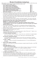
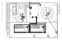
Power Supply Board Terminal Identification:
Terminal Legend Function/Description
L, G, N Connect 220VAC 50/60Hz to these terminals: L to hot, N to neutral.
+ DC –
Maximal3V - 12VDC @ 5A or 24VDC @ 5.4A to ACM8 boards.
Maximal5V - 12VDC @ 9A to ACM8 boards.
Maximal7V - 24VDC @ 9.4A to ACM8 boards.
AC FAIL
NC, C, NO
Indicates loss of AC power. Relay normally energized when AC power is present. Contact
rating 1A @ 28VDC. AC or brownout fail is reported within 1 minute of event.
BAT FAIL
NC, C, NO
Indicates low battery condition, e.g. connect to access control panel. Relay normally
energized when DC power is present. Contact rating 1A @ 28VDC. A removed battery
is reported within 5 minutes. Battery reconnection is reported within 1 minute. Low
battery threshold:
12VDC output threshold set @ approximately 10.5VDC.
24VDC output threshold set @ approximately 21VDC.
+ BAT –
Stand-by battery connections. Connect one (1) 12VDC battery to the terminals marked
[+ BAT –] for 12VDC operation
(Figs. 3 and 3a, pg. 8).
Use two (2) 12VDC batteries wired in series for 24VDC operation
(Fig. 4, pg. 9).
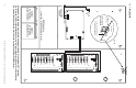
Access Power Controller Terminal Identification:
Terminal Legend Function/Description
– Power + 12VDC or 24VDC input from power supply board.
– Control + Not applicable.
TRIGGER INPUT 1-
INPUT 8 IN, GND
From normally open and/or open collector sink trigger inputs
(request to exit buttons, exit pir’s, etc.).
OUTPUT 1-
OUTPUT 8
NC, C, NO, COM
12VDC to 24VDC trigger controlled outputs:
Fail-Safe [NC positive (+) & COM Negative (–)],
Fail-Secure [NO positive (+) & COM Negative (–)],
Auxiliary output [C positive (+) & COM Negative (–)]
(When using AC power supplies polarity needs not to be observed),
NC, C, NO convert to dry form “C” 5A 24VAC/VDC rated dry outputs when fuses are
removed. Contacts shown in a non-triggered state.
FACP INTERFACE
T, + INPUT –
Fire Alarm Interface trigger input from FACP. Trigger inputs can be normally open,
normally closed from an FACP signaling circuit output
(Figs. 8-12, pgs. 13-14).
FACP INTERFACE
NC, C, NO
Form “C” relay contact rated @ 1A/28VDC for alarm reporting.