
Installation Guide

Maximal3V / Maximal5V / Maximal7V Access Power Controllers (Fused) Installation Guide - 3 -
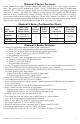
Maximal V Series Overview:
Altronix Maximal Access Power/Controllers distribute and switch power to access control systems and acces-
sories. They convert a 220VAC (working range 198VAC - 256VAC), 50/60Hz input into sixteen (16) independently
controlled 12VDC or 24VDC fuse protected outputs. These Fail-Safe/Fail-Secure power outputs may be converted
to dry form “C” contacts. The outputs are activated by an open collector sink or normally open (NO) dry trigger
input from an Access Control System, Keypad, Push Button, REX PIR, etc. Units will route power to a variety of
access control hardware devices including: Mag Locks, Electric Strikes, Magnetic Door Holders, etc. The FACP
Interface enables Emergency Egress, Alarm Monitoring, or may be used to trigger other auxiliary devices. The fire
alarm disconnect feature is individually selectable for any or all of the sixteen (16) outputs.
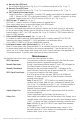
Maximal V Series Configuration Chart:
Altronix
Model Number
Power Supply
Board Output
Voltage Options
Fuse
Protected
Outputs
Individual
Output
Rating
220VAC 50/60Hz
Input
Current Draw
Power Supply
Board Input
Fuse Rating
Maximal3V
12VDC @ 5A
or 24VDC @ 5.4A
16 3.5A
1.5A
5A/250V
Maximal5V
12VDC @ 9A 2.2A
Maximal7V
24VDC @ 9.4A 3A 6.3A/ 250V
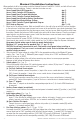
Maximal V Series Features:
• Sixteen (16) independently trigger controlled outputs. Output options:
a) Sixteen (16) Fail-Safe filtered and electronically regulated power outputs.
b) Sixteen (16) Fail-Secure filtered and electronically regulated power outputs.
c) Sixteen (16) form “C” relay outputs (rated @ 5A/28VDC or VAC).
d) Any combination of the above.
• Sixteen (16) Access Control System trigger inputs. Input trigger options:
a) Sixteen (16) normally open (NO) dry trigger inputs.
b) Sixteen (16) open collector inputs.
c) Any combination of the above.
• Sixteen (16) unswitched filtered and electronically regulated aux. power outputs (outputs are rated @ 2.5A).
• Red LEDs on ACM8 board indicate individual outputs are triggered (relays energized).
• Fire Alarm disconnect (latching or non-latching) is individually selectable for any or all of the sixteen (16) outputs.
Fire Alarm disconnect input trigger options:
a) Normally open (NO) or normally closed (NC) dry trigger input.
b) Polarity reversal input from FACP signaling circuit.
• Green LED on ACM8 board indicates FACP disconnect is triggered.
• FACP output relay indicates that FACP input is triggered.
• Power supply input is factory installed. It provides common power for both ACM8 boards and all connected
access control devices.
• ACM8 board main fuses are rated @ 10A. Output fuses are rated @ 3.5A.
• Built-in charger for sealed lead acid or gel type batteries.
- Maximum charge current is 0.7A for AL600XB220 and AL1012XB220 power supply boards.
- Maximum charge current is 3.6A for AL1024XB2V power supply board.
• Automatic switch over to stand-by battery when AC fails.
• Zero voltage drop when unit switches over to battery backup (AC failure condition).
• Short circuit and thermal overload protection with auto reset.
• Green AC input and red DC output LED indicators on power supply board(s).
• AC fail supervision (form “C” contact rated @ 1A/28VDC).
• Battery fail and battery presence supervision (form “C” contact rated @ 1A/28VDC).
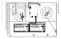
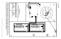
• Enclosure accommodates up to four (4) 12VDC/12AH batteries.
Enclosure dimensions (H x W x D): 26” x 19” x 6.25” (660.4mm x 482.6mm x 158.8mm).