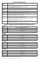
MaxFit FE Series Expandable Power Systems Models Include: MaxFit11FE - 12VDC/24VDC @ 4A. - 12VDC/24VDC @ 4A. MaxFit13FE - 12VDC/24VDC @ 4A. - 12VDC/24VDC @ 6A. MaxFit33FE - 12VDC/24VDC @ 6A. - 12VDC/24VDC @ 6A. MaxFit35FE - 12VDC/24VDC @ 6A. - 12VDC @ 10A. MaxFit37FE - 12VDC/24VDC @ 6A. - 24VDC @ 10A. MaxFit55FE - 12VDC @ 10A. - 12VDC @ 10A. MaxFit75FE - 24VDC @ 10A. - 12VDC @ 10A. MaxFit77FE - 24VDC @ 10A. - 24VDC @ 10A. Installation Guide Rev. MFE2PS072319 More than just power.
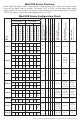
MaxFitFE Series Overview: Altronix MaxFit Expandable Power Systems provide system designers and installers with optimum power choices and the highest levels of versatility. They provide 12VDC or 24VDC via single output power supply/ charger. Includes AC fail, low battery, and battery presence monitoring. Enclosure accommodates up to four (4) 12VDC/12AH batteries. All interconnecting equipment must be UL Listed. Non Power-Limited Outputs Power-Limited Outputs Aux.
*MaxFit13FE, MaxFit33FE, MaxFit35FE, MaxFit37FE, MaxFit55FE, MaxFit75FE and MaxFit77FE: The DC output for these power supplies are not power-limited (except for eFlow4NBs in MaxFit13FE). If a powerlimited output is required in the end-product application, the DC output from the power supply must be connected to a separately Listed control unit or accessory board that provides power-limited outputs.
5. Connect devices or Altronix sub-assembly modules to be powered to the terminals marked [– DC +] (Fig. 1h, pg. 5). For auxiliary device connection, this output will not be affected by Low Power Disconnect or Fire Alarm Interface. Connect device to the terminals marked [+ AUX –] (Fig. 1f, pg. 5). Refer to page 2 for non power-limited applications. 6. For Access Control applications batteries are optional. When batteries are not used, a loss of AC will result in the loss of output voltage.
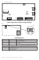
OFF --- 24V ON --- 12V ON Fig. 1 - eFlow Board configuration --- DC + 1h --- BAT + 1i 1g 10A 10A 32V 5A 250V 5A 250V AC FAIL BAT FAIL AC DELAY SHUTDOWN AC1 O N AC DC L G N NC C NO 1a NC C NO 1b 1 min. 2 hr. enable disable 1c TRIGGER EOL SUPERVISED NO GND RESET 1d 1e + AUX – 1f Power Supply Board Output Voltage Settings: OFF - 24V ON - 12V Fig. 2a --- DC + ON ON Fig.
Terminal Identification: Terminal Legend Function/Description Connect 120VAC 60Hz to these terminals: L to hot, N to neutral. Do not use terminal marked [G] (Fig. 1a, pg. 5). + DC – Refer to MaxFitFE Series Configuration Chart, pg. 2 (Fig. 1h, pg. 5). Trigger EOL Fire Alarm Interface trigger input from a short or FACP. Trigger inputs can be normally open, Supervised normally closed from an FACP output circuit (power-limited input) (Fig. 1d, pg. 5).
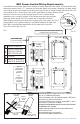
NEC Power-Limited Wiring Requirements: Power-limited and non power-limited circuit wiring must remain separated in the cabinet. All power-limited circuit wiring must remain at least 0.25” away from any non power-limited circuit wiring. Furthermore, all power-limited circuit wiring and non power-limited circuit wiring must enter and exit the cabinet through different conduits. One such example of this is shown below. Your specific application may require different conduit knockouts to be used.
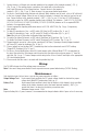
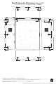
MaxFit Enclosure Dimensions (approximate): 20.5” x 16.5” x 6.25” (520.7mm x 419.1mm x 158.8mm) 1.25” (31.8mm) 7.00” (177.8mm) 7.00” (177.8mm) 1.25” (31.8mm) 1.25” (31.8mm) 6.25” (158.8mm) 1.25” (31.8mm) 16.50” (419.1mm) 1.25” (31.8mm) 0.75” (19.1mm) 1.50” (38.1mm) 1.00” (25.4mm) 1.25” (31.8mm) 1.50” (38.1mm) 8.75” (222.3mm) 8.75” (222.3mm) 20.50” (520.7mm) 8.75” (222.3mm) 8.75” (222.3mm) 0.569” (14.5mm) 1.50” (38.1mm) 1.50” (38.1mm) 1.25” (31.8mm) 1.25” (31.8mm) 1.25” (31.8mm) 1.25” (31.