
Specifications


Reference Design HFRD-25.2 (Rev.8; 01/09) Maxim Integrated Products
Page 5 of 42
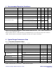
5 Recommended Operating Conditions
PARAMETER SYMBOL CONDITIONS MIN TYP MAX UNITS
Operating Ambient Temperature T
A
Note 1 0 +70
o
C
Supply Voltage V
CC
3.0 3.3 3.6 V
Transmitter Data Rate 1.25 Gbps
Digital Receiver Data Rate 1.25 Gbps
Digital Receiver Input Power 0 dBm
Bit 5 of Mode Register = 0
Continuously Repeated Interval
100
Minimum Burst On Time
Bit 5 of Mode Register = 1
Continuously repeated interval, Note 2
500
ns
Minimum Burst Off Time Continuously repeated interval, Note 2 4.5
μs
Input DC Bias Voltage V
CC
= +3.3V, TD +/- 2.0 V
Differential Input Voltage V
ID
TD +/- 200 1600 mV
p-p
SCL Clock Rate f
SCL
120 kHz
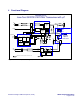
Note 1: The laser driver (MAX3643), limiting amplifier (MAX3747) and μC (ATTiny24) are rated for a
-40
o
C to +85
o
C temperature range.
Note 2: Shorter burst-on or burst-off times are tolerated but they do not cause the loops in the control to
update. Shorter intervals are, therefore, acceptable when they do not repeat continuously.
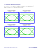
6 Typical Design Performance Data
6.1 Transmitter Performance Data
(Typical values are measured at: T
A
= +25
o
C, V
CC
= +3.3V)
PARAMETER SYMBOL CONDITIONS TYP UNITS
Power-Supply Current
Transmitter only
72 mA
Average Optical Power P
AVG
Measured at 1.25Gbps, Note 1
0 dBm
Extinction Ratio, Note 1 E
R
Set at +25
o
C 11 dB
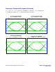
Mask Margin 0
o
C to +70
o
C, 1.25Gbps or 1244Mbps > 25 %
Off to 80% <4 ns
Burst-Enable Time
Off to 90%, Note 2 <30 ns
Burst-Disable Time Note 3 <2 ns
Maximum Initialization Time Burst mode or continuous operation, Note 4 600 ns
Power-On-Reset Time Note 5 80 ms
Center Wavelength 1310 nm
Note 1: Measured using a continuous 2
7
-1 PRBS input data pattern.