
Specifications


Reference Design HFRD-25.2 (Rev.8; 01/09) Maxim Integrated Products
Page 42 of 42
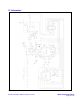
Figure 16. Board layout, layer 3.
Figure 17. Board layout, layer 4.
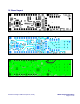
17 Layer Profile
The HFRD-25.2 reference-design board includes
controlled-impedance transmission lines. The
layer profile is based on the following
assumptions:
1.
Dielectric material is FR-4 with a
dielectric constant of ~ 4.5
2.
1oz copper foil
Single Ended Coupled
A
N.A. 8mil
B
>50mil 10mil
C
8mil 8mil
D
As Needed As Needed
Figure 18. Layer profile.
Maxim cannot assume responsibility for use of any circuitry other than circuitry entirely embodied in a Maxim product. No circuit
patent licenses are implied. Maxim reserves the right to change the circuitry and specifications without notice at any time.
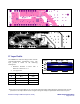
A
B
A
CORE
PREPREG
PREPREG
C
D
C