
Specifications


Reference Design HFRD-25.2 (Rev.8; 01/09) Maxim Integrated Products
Page 28 of 42
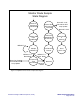
Figure 2. Simplified top-level state diagram.
Top-Level State Diagram
Initialize/
Configure
PortA, PortB
RESET
Initialize
Interrupts
And
Two-Wire
Interface
Load
EEPROM
Initialize
PWM
Precharge
Enable
Output
Configure
A
PC
Loop
Interrupt Routines
Two-Wire
Interface
EEPROM
Write
TDIS Pin
Change
Check
Operation
Mode
Monito
r
Diode
Sample
Disable
Loop
Open-Loop
Mode
APC
Loop /
Modulation
Comp.
Update
Monitors/
Memory
Figure 3
Figure 4
Figure 5
Figure 6
Figure 7
Figure 8
Figure 9
States in bold are shown in additional detail in subsequent Figures.