
Specifications


Reference Design HFRD-25.2 (Rev.8; 01/09) Maxim Integrated Products
Page 25 of 42
10.6 V
CC
Calibration
HFRD-25.2 provides a monitor of the supply
voltage. To calibrate the V
CC
monitor:
1. Set the supply voltage of the module to
3.3V (voltage at the V
CC
pin of the
module).
2. Adjust the SupplyO value (EEPROM
0Eh, typical value = 1Ch (28)), until the
digital value reported in SupplyVH and
SupplyVL (SRAM 70h, 71h) is equal to
D7h (215). Please note that the power or
reset signal should be cycled after each
change in the SupplyO value.
V
CC
is monitored internally by selecting the
supply as the reference, and then doing an A/D
conversion on the ATTiny24 voltage reference
(approximately 1.1V). Using this method requires
no external pin allocation, but results in some
inaccuracy of the monitor value. A compensation
equation is applied in firmware to improve the
linearity of the monitor. If the RSSI feature or
support of continuous and burst-mode operation is
not needed, then a pin should be allocated to
supply voltage monitoring for improved linearity.
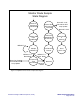
10.7 Temperature Calibration
The ATTiny24 includes an internal sensor for
temperature measurement. The monitor requires
calibration for proper operation of the Instant-On
lookup table and for proper operation of the linear
modulation temperature compensation. The
monitor is calibrated with the following steps:
1. Determine the slope/scaling factor by
doing a two-temperature calibration (any
two temperature points, T1 and T2, where
T2 > T1 + 10
o
C).
2. Set the ambient temperature to T1 and
record the A/D conversion result (TR
T1
)
of the temperature (SRAM TemperVH
(6Eh), TemperVL (6Fh))
3. Increase the ambient temperature to T2
and record the A/D conversion result
(TR
T2
) of the temperature (SRAM
TemperVH (6Eh), TemperVL (6Fh))
4. Calculate the slope (TemperS) of the
monitor, which is given by:
⎟
⎟
⎠
⎞
⎜
⎜
⎝
⎛
−
−
⋅=
12
12
100
TT
TRTR
TT
TemperS
5. Store the TemperS value (EEPROM 0Dh)
and cycle the power or reset signal.
6. Adjust the temperature offset (TemperOH
(EEPROM 0Ch), TemperOL (EEPROM
0Bh)) value until the value in CalTemp
(SRAM 75h) is equal to the current
ambient temperature (in degrees C) plus
40. Please note that the power or reset
signal should be cycled after each change
in the temperature offset value.
The value in CalTemp (SRAM 77h) will now
report the temperature in degrees C with an offset
of 40 (e.g. 0h (0) = -40
o
C, 41h (65) = 25
o
C).
10.8 Instant-On Lookup Table
HFRD-25.2 includes an Instant-On LookupTable
to set the bias current’s initial value as
temperature changes (EEPROM 10h (16) to 33h
(51); see Section 10.3). A memory location is
allocated for storing a new bias current value in
4
o
C steps for temperature from -40
o
C to +100
o
C.
On power-on, the device will precharge the bias
current to the level defined in the lookup table.
This feature allows for proper output levels at the
first or second burst after the transmitter is
enabled (power-on or re-enable from a disable
state). If the first burst of data occurs more than
600ns after the driver has been enabled (by POR
or external control), then the initialization time is
zero. The first burst is at the calibrated level. If the
first burst occurs less than 600ns after the
MAX3643 has been enabled, then the first burst
will not have reached the final calibrated value. If