
Specifications


Reference Design HFRD-25.2 (Rev.8; 01/09) Maxim Integrated Products
Page 24 of 42
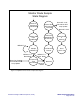
7Fh
to
AFh
Microcontroller Stack SRAM
B0h
to
E0h
Program Accessed SRAM
10.4 PWM Outputs
Two 8-bit PWM outputs from the ATTiny24 are
used to set the bias and modulation currents of the
MAX3643 laser driver. By passing the PWM
output through a lowpass filter and resistive
divider, a low-noise, digitally-adjustable voltage
is generated. The voltage output is given by:
⎟
⎠
⎞
⎜
⎝
⎛
⋅
⎟
⎠
⎞
⎜
⎝
⎛
−
⋅=
k
kPWMV
VV
CCOUT
1.20
1.5
255
255
Where PWMV is the 0 to 255 setting of the PWM
output
Please note that as the PWMV value increases, the
output voltage will decrease. The firmware inverts
this relationship for all PWM calibration values
(EEPROM address 01h, 07h, 08h) so that
increasing values equate to increasing currents.
The output voltage related to the user input
calibration value (CalVal) is therefore:
⎟
⎠
⎞
⎜
⎝
⎛
⋅
⎟
⎠
⎞
⎜
⎝
⎛
⋅=
k
kCalVal
VV
CCOUT
1.20
1.5
255
The approximate bias and modulation current
associated with a given PWM value (assuming no
compensation is applied) is given by:
⎟
⎠
⎞
⎜
⎝
⎛
⋅
⎥
⎦
⎤
⎢
⎣
⎡
⎟
⎠
⎞
⎜
⎝
⎛
⋅
⎟
⎠
⎞
⎜
⎝
⎛
−
⋅=
kk
kPWMV
VI
CCBIAS
5.1
88
1.20
1.5
255
255
⎟
⎠
⎞
⎜
⎝
⎛
⋅
⎥
⎦
⎤
⎢
⎣
⎡
⎟
⎠
⎞
⎜
⎝
⎛
⋅
⎟
⎠
⎞
⎜
⎝
⎛
−
⋅=
kk
kPWMV
VI
CCMOD
1
88
1.20
1.5
255
255
In terms of calibration value:
⎟
⎠
⎞
⎜
⎝
⎛
⋅
⎥
⎦
⎤
⎢
⎣
⎡
⎟
⎠
⎞
⎜
⎝
⎛
⋅
⎟
⎠
⎞
⎜
⎝
⎛
⋅=
kk
kCalVal
VI
CCBIAS
5.1
88
1.20
1.5
255
⎟
⎠
⎞
⎜
⎝
⎛
⋅
⎥
⎦
⎤
⎢
⎣
⎡
⎟
⎠
⎞
⎜
⎝
⎛
⋅
⎟
⎠
⎞
⎜
⎝
⎛
⋅=
kk
kCalVal
VI
CCMOD
1
88
1.20
1.5
255
10.5 V
CC
Compensation of PWM
Outputs
The PWM outputs provide a simple and very low-
cost adjustable voltage source for setting the bias
and modulation current; however, as seen in the
equations above, the bias and modulation currents
will scale with supply voltage. The firmware
provided with HFRD-25.2 incorporates PWM
output value compensation to account for changes
in V
CC
. If this feature is enabled (see Section
10.2), the controller will sample the supply
voltage and apply a correction factor to the PWM
digital value. A scaling byte EEPROM 03h (see
Section 10.3) is also provided to fine-tune the
amount of V
CC
compensation applied to the PWM
value.
The proper operation of this feature requires that
V
CC
be calibrated (see Section 10.6).