
Specifications


Reference Design HFRD-25.2 (Rev.8; 01/09) Maxim Integrated Products
Page 22 of 42
10.3 Memory Summary
The ATTiny24 microcontroller incorporates 128bytes of SRAM and 128bytes of EEPROM. Tables 2 and 3
list the EEPROM and SRAM memory allocations.
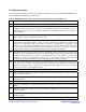
Table 2: EEPROM Memory (00h to 7Fh, Hexadecimal Is Indicated by the Trailing “h”.)
Byte Name/Definition
00h MODE: Mode of Operation Control Byte (See Table 1)
01h MODSET: Stores the calibrated modulation PWM output value which relates to the desired
modulation output current (Section 10.4). The actual PWM output value is adjusted by the V
CC
compensation (Section 10.5) and modulation temperature compensation (Section 10.9) features, if
they are enabled.
02h APCSET: Stores the calibrated value for the desired monitor diode current (APC Set Point) where:
Monitor Diode Current = (APCSET•(1.1)/(255))/1.5k
03h VcompS: Stores a percentage value (0 to 255 for 0% to 255%) that can be used to scale the V
CC
compensation of the PWM outputs. A value of 100 is nominal 100% compensation. Small values
provide less compensation, while large values provide more compensation. For example, if the
current value is 100% but the modulation current needs to be increased at low supply voltage, the
VcompS value should be increased. This value will typically only need to be set once for a given
design and then stored in every module without the need for individual recalibration.
04h KFactorSH: K-Factor set point. This is input as a percentage value (0 to 255 for 0% to 255%). This
percentage value is multiplied by the bias current monitor digital value and then combined with the
modulation PWM output value to increase the modulation current. This effectively increases the
modulation current as the temperature increases due to the increase in bias current. K-factor
compensation is disabled by setting 04h to 00h. See Section 10.9 for additional details.
05h KFactorSL: Linear modulation temperature compensation value. This is input as a percentage value
(0 to 255 for 0% to 255%). This percentage value, multiplied by the temperature and minus the
temperature start point (06h), is applied to the modulation PWM output to increase the modulation
current. See section 10.10 for additional details.
06h K2TempS: Start point for linear temperature compensation. See Section 10.10 for additional details.
07h MMax: Maximum modulation PWM value which sets the maximum modulation current. See Section
10.4 for additional details.
08h BMax: Maximum bias PWM value which sets the maximum bias current. See Section 10.4 for
additional details.
09h TrackErrC: Tracking error compensation factor. See Section 10.11 for additional details.
0Ah TETempC: Tracking error compensation temperature start point. See Section 10.11 for additional
details.
0Bh TemperOL: Temperature offset low byte for temperature calibration routine. See Section 10.7 for
additional details.
0Ch TemperOH: Temperature offset high byte for temperature calibration routine. See Section 10.7 for
additional details.
0Dh TemperS: Scaling factor for temperature calibration routine. See Section 10.7 for additional details.