
Specifications


Reference Design HFRD-25.2 (Rev.8; 01/09) Maxim Integrated Products
Page 21 of 42
10 Controls/Features
10.1 Overview
Through the use of a low-cost microcontroller,
HFRD-25.2 provides many control options and
monitoring features. These features and monitors
are explained in the sections that follow.
10.2 Modes of Operation
The HFRD-25.2 design can operate in a variety of
different modes (burst mode, continuous mode,
open loop, etc.). The mode of operation is set by
byte 00 (MODE) located in EPROM memory.
Each bit in byte 00 corresponds to a different
feature or mode of operation. Table 1 summarizes
the MODE bit definitions. A change to the MODE
setting will only take effect after a power cycle or
toggle of the reset signal.
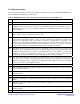
Table 1: MODE Byte (EEPROM Address 00h)
Bit Definition
0 0 - Burst-Mode Operation. Sampling of the monitor diode current, for APC loop adjustments, is
triggered by the MAX3643 BENOUT output.
1 - Continuous-Mode Operation (TX_BRST must be high). Monitor diode current is periodically
sampled for APC loop adjustments.
1 0 - Closed Loop (APC loop controls the bias current).
1 - Open-Loop Mode. Bias Current is set through the temperature-indexed lookup table (see Section
10.8 for additional details). V
CC
compensation of modulation and bias current and temperature
compensation of modulation currents are still active if enabled.
2 0 - Only load calibration values (EEPROM Addresses 01h to 0Ah) when power or reset are cycled.
1 - Periodically load calibration values (EERPOM Addresses 01h to 0Ah).
3 0 - Software Enable. Normal operation.
1 - Software Disable. If set to one, the laser driver will be disabled but the monitor values will continue
to update. This mode is useful when doing the initial calibration of the V
CC
and temperature monitors.
4 0 - V
CC
compensation of PWM outputs Enabled. Note PWM compensation of bias current is only
applied when in open-loop mode. When in closed-loop mode, the APC loop automatically adjusts the
PWM value for changes in V
CC
.
1 - V
CC
compensation of PWM outputs Disabled.
5 0 - Track and update APC loop for all bursts. Note the system can only reliably detect bursts 100ns in
length or longer. Continuously repeated bursts shorter than 100ns will create significant offsets in the
average power.
1 - Ignore bursts shorter than approximately 500ns.
6 0 - Tracking Error Compensation Disabled.
1- Tracking Error Compensation Enabled. See Section 10.11 for additional details.
7 0 - PWM Preboost Enabled. The preboost allows the PWM output filter to charge faster.
1- PWM Preboost Disabled.