
Specifications


Reference Design HFRD-25.2 (Rev.8; 01/09) Maxim Integrated Products
Page 20 of 42
9 Application Information
9.1 Design Details
HFRD-25.2 provides PON modules designers
with a simple, low-cost, high-performance and
feature-rich reference design for GEPON
ONT/ONU modules. The design can also be used
as a reference for GPON and BPON designs as
many of the features and components are
compatible with those standards.
The HFRD-25.2 reference design also includes
the complete and documented firmware code for
the ATMEL ATTiny24 μC, which is used in the
design. See Section 11 for additional details about
the firmware.
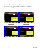
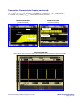
9.2 Burst Enable Time
The HFRD-25.2 design will typically burst on to
90% in less than 30ns (with a TTL TX_BRST
input) which is sufficient for GEPON
applications; however, GPON modules will often
require burst on-times of less than 10ns. Burst on-
times less than 4ns can be obtained when using
the MAX3643 by adding a diode on the OUT- pin
and using a PECL TX_BRST input (See the
HFRD-22.3 document for placement of the
diodes, part numbers, and performance results.).
As HFRD-25.2 was intended for use in GEPON
applications, the diode on OUT- was omitted from
this design to reduce the bill-of-materials cost.
9.3 PON Compliance
This reference design aids GEPON ONT module
designers and is not intended to replace the entire
design process. The designer is responsible to
evaluate the reference design and modify it as
necessary to meet the specification for each
particular project. The designer must also
carefully consider eye safety and EMI issues
related to the specific application.
9.4 Gerber Files
The Gerber files for this reference design are
available by contacting the Maxim
Optoelectronics group by email to:
https://support.maxim-
ic.com/tech_support/submit_question.mvp?pl_id=
5. The Gerber files are provided at no cost but no
technical support or modification to the Gerber
files will be provided. The Gerber files are also
not guaranteed and should be checked, reviewed,
and adjusted as necessary for each application and
assembly process.
When using the HFRD-25.2 Gerber files please
note:
1. The trace that connects pin 11 of the
optical subassembly to the RSSI input of
the μC was cut. This feature was not
available in the current version of the
optical subassembly.
2. The package for the optical device was
changed after the tapeout of the HFRD-
25.2 board. The layout is compatible with
the new optical package but any new
designs should be modified to match the
current optical package.
9.5 Layout Considerations
Differential transmission lines are used on the
HFRD-25.2 PCB board. Changing the PCB layer
profile (Section 17) can affect the impedance of
these transmission lines and the performance of
the reference design. If the layer profile is
changed, the transmission line dimensions should
be recalculated.