
Datasheet


DS1631/DS1631A/DS1731
8 of 15
provides user access to the temperature register. Bits 3 through 0 of the temperature register are
hardwired to 0. When the device is configured for 12-bit resolution, the 12 MSbs (bits 15 through 4) of
the temperature register contain temperature data. For 11-bit resolution, the 11 MSbs (bits 15 through 5)
of the temperature register contain data, and bit 4 is 0. Likewise, for 10-bit resolution, the 10 MSbs (bits
15 through 6) contain data, and for 9-bit the 9 MSbs (bits 15 through 7) contain data, and all unused LSbs
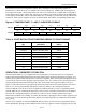
contain 0s. Table 4 gives examples of 12-bit resolution output data and the corresponding temperatures.
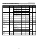
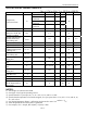
Figure 4. TEMPERATURE, T
H
, AND T
L
REGISTER FORMAT
bit 15 bit 14 bit 13 bit 12 bit 11 bit 10 bit 9 bit 8
MS Byte
S 2
6
2
5
2
4
2
3
2
2
2
1
2
0
bit 7 bit 6 bit 5 bit 4 bit 3 bit 2 bit 1 bit 0
LS Byte
2
-1
2
-2
2
-3
2
-4
0 0 0 0
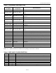
Table 4. 12-BIT RESOLUTION TEMPERATURE/DATA RELATIONSHIP
TEMPERATURE
(°C)
DIGITAL OUTPUT
(BINARY)
DIGITAL OUTPUT
(HEX)
+125 0111 1101 0000 0000 7D00h
+25.0625 0001 1001 0001 0000 1910h
+10.125 0000 1010 0010 0000 0A20h
+0.5 0000 0000 1000 0000 0080h
0 0000 0000 0000 0000 0000h
-0.5 1111 1111 1000 0000 FF80h
-10.125 1111 0101 1110 0000 F5E0h
-25.0625 1110 0110 1111 0000 E6F0h
-55 1100 1001 0000 0000 C900h
OPERATION—THERMOSTAT FUNCTION
The thermostat output (T
OUT
) is updated after every temperature conversion, based on a comparison
between the measured digital temperature and user-defined upper and lower thermostat trip points. T
OUT
remains at the updated value until the next conversion completes. When the measured temperature meets
or exceeds the value stored in the upper trip-point register (T
H
), T
OUT
becomes active and remains active
until the measured temperature falls below the value stored in the lower trip-point register (T
L
) (see
Figure 5). This allows the user to program any amount of hysteresis into the output response. The active
state of T
OUT
is user-programmable through the polarity bit (POL) in the configuration register.
The user-defined values in the T
H
and T
L
registers (see Figure 4) must be in two’s complement format
with the MSb (bit 15) containing the sign bit (S). The T
H
and T
L
resolution is determined by the R0 and
R1 bits in the configuration register (see Table 6), so the T
H
and T
L
resolution matches the output
temperature resolution. For example, for 10-bit resolution bits 5 through 0 of the T
H
and T
L
registers read
out as 0 (even if 1s are written to these bits), and the converted temperature is compared to the 10 MSbs
of T
H
and T
L
.
The T
H
and T
L
registers are stored in EEPROM; therefore, they are NV and can be programmed prior to
device installation. Writing to and reading from the T
H
and T
L
registers is achieved using the Access TH