
Datasheet


DS1631/DS1631A/DS1731
5 of 15
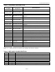
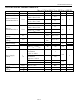
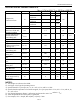
AC ELECTRICAL CHARACTERISTICS
(V
DD
= 2.7V to 5.5V; T
A
= -55°C to +125°C.)
PARAMETER SYMBOL CONDITION MIN TYP MAX UNITS NOTES
9-bit resolution 93.75
10-bit
resolution
187.5
11-bit
resolution
375
Temperature
Conversion Time
t
TC
12-bit
resolution
750
ms
SCL Frequency f
SCL
0 400 kHz
Bus Free Time
Between a STOP and
START Condition
t
BUF
1.3 µs 5
START and Repeated
START Hold Time
from Falling SCL
t
HD:STA
0.6 µs 5, 6
Low Period of SCL t
LOW
1.3 µs 5
High Period of SCL t
HIGH
0.6 µs 5
Repeated START
Condition Setup Time
to Rising SCL
t
SU:STA
0.6 µs 5
Data-Out Hold Time
from Falling SCL
t
HD:DAT
0
0.9 µs 5
Data-In Setup Time to
Rising SCL
t
SU:DAT
100 ns 5
Rise Time of SDA and
SCL
t
R
20 + 0.1C
B
1000 ns 5, 7
Fall Time of SDA and
SCL
t
F
20 + 0.1C
B
300 ns 5, 7
STOP Setup Time to
Rising SCL
t
SU:STO
0.6 µs 5
Capacitive Load for
Each Bus Line
C
B
400 pF
I/O Capacitance C
I/O
10 pF
Input Capacitance C
I
5 pF
Spike Pulse Width that
can be Suppressed by
Input Filter
t
SP
0 50 ns
NOTES:
1) All voltages are referenced to GND.
2) See Figure 2 for Typical Operating Curves.
3) Specified with T
OUT
pin open; A
0
, A
1
, A
2
= 0V or V
DD
; and f
SCL
≥ 2Hz.
4) Specified with temperature conversions stopped; T
OUT
pin open; SDA = V
DD
; SCL = V
DD
; and A
0
, A
1
,
A
2
= 0V or V
DD
.
5) See Timing Diagram in Figure 3. All timing is referenced to 0.9 x V
DD
and 0.1 x V
DD
.
6) After this period the first clock pulse is generated.
7) For example, if C
B
= 300pF, then t
R
[min] = t
F
[min] = 50ns.