
Installation Sheet

INSTALLATION INSTRUCTIONS
PLEASE READ CAREFULLY AND SAVE THESE
INSTRUCTIONS, AS YOU MAY NEED THEM AT LATER
DATE.
CAUTION - Turn off the main power at he circuit breaker before installing
The fixture, in order to pre vent possible
shock.
Remove the fixture and the mounting package from the box and mak e
sure that no parts are missing by refe rencing th e
illustrations on the
installation instruction.
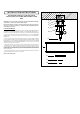
FOR CEILING MOUNT
1. A) Place the #8-32 HEX NUTS (3) onto the #8-32 FIXTURE MOUNTING SCREWS (4)
and attach the FIXTURE MOUNTING SCREWS to the MOUNTING BRACKET (2), or
Universal mounting plate (whichever is provided).Do not tighten the HEX NUTS at this time.
2. Pull the power supply wires out from the OUTLET BOX (1), and mount the MOUNTING
BRACKET (2) or the universal mo unting plate to the OUTLET BOX, using MOUNTING
SCREWS (10).
3. At tach the power supply wires to the fixture load wi res by connecting BLACK to BLACK
(6), and WHITE to WHIT
E (5). Attach the POWE R SUPPLY GROUND WIRE (7) from the
OUTLET BOX (1) an d th e F IXTURE GROUND WIRE (8) from the fix ture to the GRE EN
GROUND SC REW (9) on the MOUNTING BRACKET (2) or connect both wire s together
using the correct size of wire con nectors.
4. Placing the CANOPY (11) on the fixture over the OUTLET BOX (1) and onto the fixture
mounting screws (4), and adjust the #5-32 fixture mounting screws until they protrude out
f rom the CANOPY 1/4 . Remove the CANOPY and secure the position of the fixture
mounting
screws by tigh tening the HEX NUT(S) (3) against the MOUNTING BRACKET (2). Place the
CANOPY back onto the fixture mounting screws and secure into place using the DECORATI VE
NUTS (12) provided.
5. Screw in light bulbs that do not exceed the maximum wattage specified on the fix ture's
wattage rating lab el into the socket(s) on the fixture.
INTALLATION COMPLETED
7
9
10
3
5
1
4
2
6
8