
Installation Guide

Page 1 / 2
CEILING FLUSH INSTALLATION INSTRUCTIONS
READ AND SAVE THESE INSTRUCTIONS
TOOLS AND MATERIALS REQUIRED
Adjustable wrench Wire cutters
Flat blade screwdriver Step ladder
Wiring supplies as required by electrical codes.
CAUTION:
Refer to the section tilled ELECTRICAL
CONNECTIONS before assembling your lighting fixture. If you feel
you do not have electrical wiring experience, refer to a do it yourself
wiring handbook or have your fixture installed by a licensed
electrician.
GENERAL
1. To ensure the success of the installation, be sure to read these
instructions and review the diagrams thoroughly before
beginning.
2. All electrical connections must be in accordance with local
codes, ordinances or the National Electrical Code. If you are
unfamiliar with methods of installing electrical wiring,secure
the services of a qualified licensed electrician.
3.
These fixtures are intended to be mounted to a 4 x 2 1/8 deep
metal octagon outlet box.The box must be directly supported
by the building structure.
4.
Before starting the installation, disconnect the power by turning
off the circuit breaker or by removing the fuse at the fuse box.
Turning the power off using the light switch is not sufficient to
prevent electrical shock.
2.
3.
4.
1.
2.
3.
4.
1.
NOTE: The important safeguards and instructions appearing in this
manual are not meant to cover all possible conditions and situations
that may occur. It must be understood that common sense, caution,
and care are factors which cannot be built into any product. These
factors must be supplied by the person(s) caring for and operating the
fixture.
UNPACK THE FIXTURE
Mounting hardware package Fixture assembly(s)
Check the content of the box. You should receive:
Glass shade or shade assembly
NOTE: FIRST TURN OFF ELECTRICITY
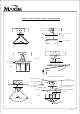
Refer to figures for illustration of typical fixture parts for assembly
If you are replacing an existing fixture, disconnect and remove
the old fixture. Expose the wiring in the outlet box
Some models require the installation of two mounting screw on
the crossbar as shown in the illustration. If not already installed,
install them on the cross bar as shown. Fasten the cross bar to
outlet box using the two screws supplied with outlet box. On
some models, a nipple may need to be installed.
Attach grounding wire (green or bare copper) from the supply
circuit to the mounting bracket with the green grounding
attachment screw provided .Some models have a grounding wire
attached to the fixture.For models that employ a green or bare
copper grounding wires.It will necessary to connect the green or
bare copper grounding wire to the grounding conductor of the
supply circuit.
Make electrical connections SEE BELOW.
ELECTRICAL CONNECTIONS
To make electrical connections:
Fixtures will have a black and white wire or a two wire power supply cord.
Split the power supply cord wires into separate leads. Connect the half of
the cord that is ribbed or the white wire to the white wire of the supply
circuit. Connect the smooth half of the wire (the half with markings) or
the black wire to the black wire of the supply circuit. Connect the green or
bare copper wire to the CROSSBAR grounding screw and the grounding
conductor of the supply circuit. On fixtures that do not use a crossbar
connect fixture ground wire to supply ground wire with wire connectors.
Use U.L. Listed wire connectors suitable for the size, type and number of
conductors.No loose strands or loose connectors should be present. Secure
wire connections with U.L. listed electrical tape.
F I N A L A SS E M B LY
5.
Spread the electrical splices so that the black wires are on the one side
of the outlet box and the white wires are on the other side.
Raise fixture to outlet box and secure with screws, acorn nuts or
finial.On models that have a ceiling pan with keyhole slots, the head
of the screw will pass through the larger end of the keyhole slot.The
pan must then be turned slightly so that the screw head is over the
smaller part of the opening of the keyhole slot. Tighten screws once
pan is in place.
Install light bulbs (not provided) Refer to the lamping
label located near the lamp holder, for recommended maximum
CAUTION:
wattage - DO NOT EXCEED RECOMMENDED WATTAGE!
On models with disassembled shade, install shade and secure with
screws or finial. Please refer to illustrations. On some models the
shade is installed without hardware. On these models, line up vertical
slot on shade with raised areas on the ceiling pan. Raise shade into
ceiling pan and then turn glass shade on clockwise direction about 1/4
turn until it tightens.
Restore electricity and check the operation of your lighting fixture.