
Owner's manual


clock cycle has been added to each MOVX instruction (for data access) and to the instruction that follows the MOVX (for code fetch)
to account for potential page misses. The sample code listings have been marked accordingly with ‘+D’ to indicate a data access
page-miss and ‘+C’ to indicate a code-fetch page-miss. Thus, in the case of back-to-back MOVX operations, the second MOVX oper-
ation has two clock cycles added (‘+CD’), one associated with the code fetch and one associated with the data access.
The sample code listings for these programs appear on the following pages.
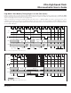
Program 1 listed below is original code written for an 8051 and utilizes a single data pointer.
Program 2 uses the dual data pointer feature.
Program 3 uses the dual data pointer with autoincr
ement enhancement.
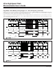
Program 4 uses the dual data pointer with autotoggle enhancement.
Program 5 uses the dual data pointer with autoincrement and autotoggle enhancements.
The relevant register and bit locations are summarized as follows:
DPL 82h Low-byte original DPTR
DPH 83h High-byte original DPTR
DPL1 84h
Low-byte new DPTR
DPH1 85h High-byte new DPTR
DPS 86h SEL bit = DPS.0
AID bit = DPS.4
TSL bit = DPS.5
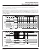
PROGRAM 1: 64-BYTE BLOCK MOVE (WITHOUT DUAL DATA POINTER)
; SH and SL are high and low byte source address.
; DH and DL are high and low byte of destination address.
; For cycle counts:
; HSM = High-Speed Microcontroller
; UHSM = ultra-high-speed microcontroller
# HSM/UHSM CYCLES
MOV R5, #64 ; NUMBER OF BYTES TO MOVE 2/2
MOV DPTR, #SHSL ; LOAD SOURCE ADDRESS 3/3
MOV R1, #SL ; SAVE LOW BYTE OF SOURCE 2/2
MOV R2, #SH ; SAVE HIGH BYTE OF SOURCE 2/2
MOV R3, #DL ; SAVE LOW BYTE OF DESTINATION 2/2
MOV R4, #DH ; SAVE HIGH BYTE OF DESTINATION 2/2
MOVE:
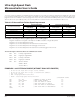
Table 6-9. Enhanced Data Pointer Speed Improvement
D S80C3 2 0 HIGH SPE ED DS8 9C4 2 0 ULTRA-HIGH S PE E D
DATA POINTER OP ERATION
CLOCK CYCLES
(4CLKS/ MCLK)
E X E CUTION T IM E
(AT 33MHZ)
CLOCK CYCLES
E X E CUTION T IM E
(AT 33MHZ)
Single Dat a Po i n t er 186 9 x 4 22 7 µ s 19 3 3 59µs
Dual Data Po int er 109 8 x 4 13 3 µ s 12 9 1 39µs
Dual D a ta Poi nt er w/ AID — — 116 9 35µs
Dual Data Po int er w /TSL — — 91 0 28µs
Dual Data Po int er w / AID,TS L — — 78 2 24µs
Ultra-High-Speed Flash
Microcontroller User’s Guide
Maxim Integrated
6-23