
Owner's manual

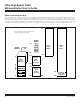


6-10
Ultra-High-Speed Flash
Microcontroller User’s Guide
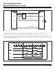
Figure 6-5 shows external memory cycles for the page mode 1 bus structure. The first case illustrates a back-to-back MOVX execu-
tion sequence for one-cycle page mode (PAGES 1:0 = 00b). PSEN remains active during page-hit cycles, and page misses are forced
during and after MOVX executions, independent of the most significant byte of the subsequent addresses. The second case illustrates
a MOVX execution sequence for two-cycle page mode (PAGES 1:0 = 01b). PSEN is active for a full clock cycle in code fetches. Note
that the page misses in this sequence are caused by changing of the most significant byte of the data address. The thir
d case illus-
trates a MOVX execution sequence for four-cycle page mode (PAGES 1:0 = 10b). There is no page-miss in this execution cycle, as the
most significant byte of the data address is assumed to match the last program address.
Internal Memory Cycles
XTAL1
ALE
Port 0
Port 2
DataData
Inst
MSB MSB MSB MSBMSB LSB LSB LSB LSB LSB LSB
InstInst
External Memory Cycles
Page MissPage HitPage Miss Data Access Data Access
PAGES=00
ALE
PSEN
MOVX
Inst
Data
Page Miss Page MissData AccessPage Hit
MSBAdd LSB Add LSB Add MSBAdd MSBAddLSB Add
PAGES=01
Port 0
Port 2
MSBAdd LSB Add LSB Add
Inst
Data
Port 2
Port 0
PSEN
ALE
Page Miss Data Access
RD / WR
RD / WR
PAGES=10
RD / WR
MOVX MOVX
LSB
PSEN
MOVX executed
MOVX executedMOVX executed
next instruction
Figure 6-5. Page Mode 1 External Memory Cycle (CD1:0 = 10b)
Maxim Integrated