
Owner's manual


5-8
Ultra-High-Speed Flash
Microcontroller User’s Guide
SYSCLK
ALE
PSEN
PORT 2
PORT 0
LSBLSB LSB
RET
LSB LSB2200
NOP
MSB ADDRESS MSB ADDRESS
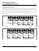
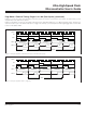
Figure 5-8. Nonpage Mode: RET – NOP
SYSCLK
ALE
PSEN
PORT 2
PORT 0
MSB ADDRESS
LSBLSB 71 LSB
ACALL NOP
LSB3300
MSB ADDRESS
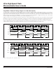
Figure 5-7. Nonpage Mode: ACALL – NOP
Figure 5-7 illustrates an ACALL instruction (2 bytes, two cycles) with a destination address residing on a different 256-byte page. This
is indicated only by the MSB address change on port 2. The memory cycle duration remains constant.
Figure 5-8 shows execution of the RET instruction (1 byte, three cycles). Because the cycle count of the RET instruction exceeds the
byte count, two stall cycles (“dummy” fetches) are inserted to allow execution to complete. In this example, the return address and the
RET instruction are on different 256-byte pages (signified by the MSB address change on port 2).
Maxim Integrated